
Electrostatic atomizer and air conditioner

Inactive Publication Date: 2010-12-16
MITSUBISHI ELECTRIC CORP
View PDF23 Cites 14 Cited by
  • Summary
  • Abstract
  • Description
  • Claims
  • Application Information

AI Technical Summary

Benefits of technology

[0011]The present invention is done in order to solve the above problems, and aims to provide an electrostatic atomizer which can guide rapidly and steadily water supplied from the water supply means to the top end atomizing unit of the atomizing electrode and can obtain stably a large amount of electrostatic mist, and an air conditioner which can stably release plenty of the electrostatic mist to the indoors using the electrostatic atomizer.

Problems solved by technology

Further, since the mist is charged due to the high voltage, it tends to approach to a person who generates a potential difference.

Method used


Image

  • Electrostatic atomizer and air conditioner
  • Electrostatic atomizer and air conditioner
  • Electrostatic atomizer and air conditioner

Examples


embodiment 1

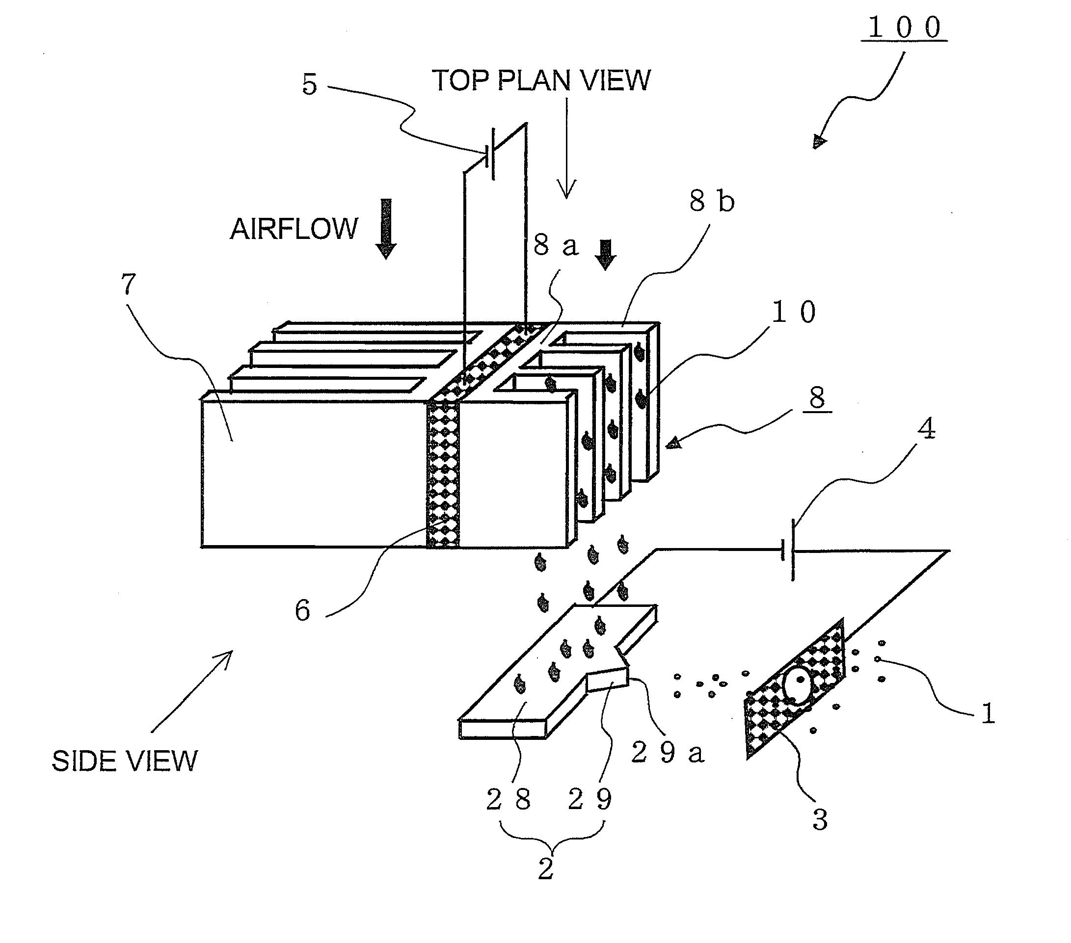
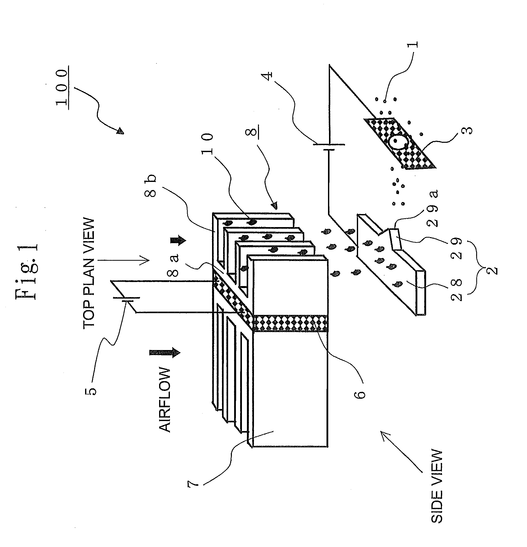
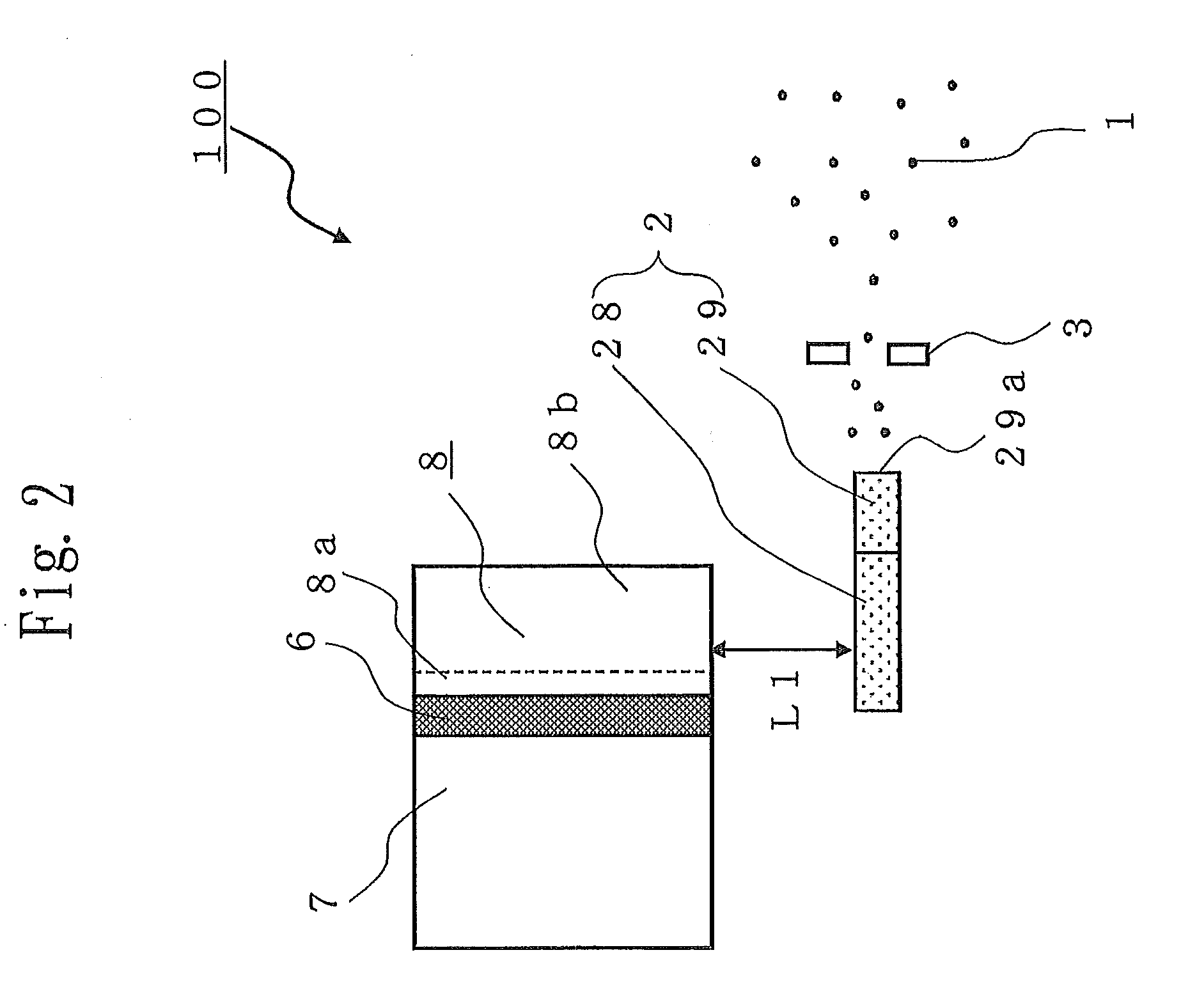
[0031]FIGS. 1 to 17 show the first embodiment; first, with reference to FIGS. 1 to 4, a configuration of an electrostatic atomizer 100 will be explained. The electrostatic atomizer 100 of the present embodiment includes an atomizing electrode 2 and a counter electrode 3 to generate an electrostatic mist 1 of nanometer (10−9 m) size as shown in FIG. 1.

[0032]The atomizing electrode 2 includes a trunk unit 28 and a top end atomizing unit 29 which are both plate-shaped, and water supplied to the trunk unit 28 is moved (delivered) to the top end atomizing unit 29. The top end (the projected end) of the top end atomizing unit 29 is arranged so as to be directed to the counter electrode 3. For the atomizing electrode 2, porous body is used as material; however, here, in particular, foam metal which is metal porous body having three-dimensional net structure is used. These will be explained later in detail.

[0033]Between the atomizing electrode 2 and the counter electrode 3, high voltage of ...


PUM


Abstract

An atomizing electrode includes: a trunk unit made to be tabular-shaped and almost rectangular-shaped for receiving water dropped from water supply means in a direction of gravitational force and delivering the water; and a top end atomizing unit which is a plate-shaped projection formed so as to be projected from a side surface of the trunk unit and formed unitedly with the trunk unit. The trunk unit of the atomizing electrode extends a long-side direction in a horizontal direction, is provided below the cooling unit with a space of a predetermined distance so as not to contact the cooling unit, and is arranged so that when the cooling unit is projected in the direction of gravitational force, a width of the cooling unit in a horizontal direction should be included in a width of a long-side direction of a top surface of the trunk unit exposed to the cooling unit.

Description

BACKGROUND OF THE INVENTION[0001]1. Field of the Invention[0002]The present invention relates to an electrostatic atomizer for generating mist of nanometer size (particulate water) by the electrostatic atomization phenomena, and an air conditioner mounting the electrostatic atomizer.[0003]2. Discussion of the Background[0004]Conventionally, an electrostatic atomizer has been proposed, in which ceramic porous body delivering water is made to stand up in a water reserving unit, water in the water reserving unit is sucked up to the upper end by capillary action, and by applying high voltage to the ceramic porous body, at the upper end which is pin-shaped, sucked water is crushed and released in the air. It has been necessary for the user to supply water to the water reserving unit (for example, refer to Patent Document 1).[0005]Further, another electrostatic atomizer has been proposed, in which a metal bar itself is cooled, water in the air is condensed directly on the surface of the m...

Claims


Application Information

Patent Timeline
Patent Type & Authority Applications(United States)
IPC IPC(8): B05B5/16F24F3/16
CPCB05B5/057B05B5/16F24F6/12
Inventor MORIOKA, REIJISAKAI, TAKAHIRO
Owner MITSUBISHI ELECTRIC CORP
Learn More