
Method and System for Chopped Antenna Impedance Measurements with an RFID Radio

a technology of impedance measurement and radio, which is applied in the direction of resistance/reactance/impedence, transmission monitoring, instruments, etc., can solve the problems of receiver desensitization and intermodulation distortion, receiver transmission frequency and reader reception frequency are essentially identical, and receivers are overloaded

Active Publication Date: 2010-12-02
SYMBOL TECH LLC
View PDF11 Cites 42 Cited by
  • Summary
  • Abstract
  • Description
  • Claims
  • Application Information

AI Technical Summary

Benefits of technology

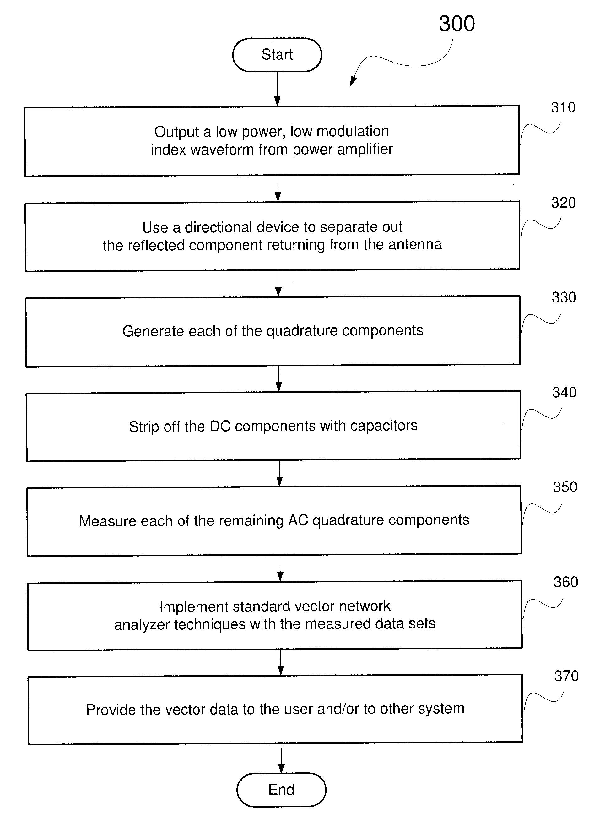
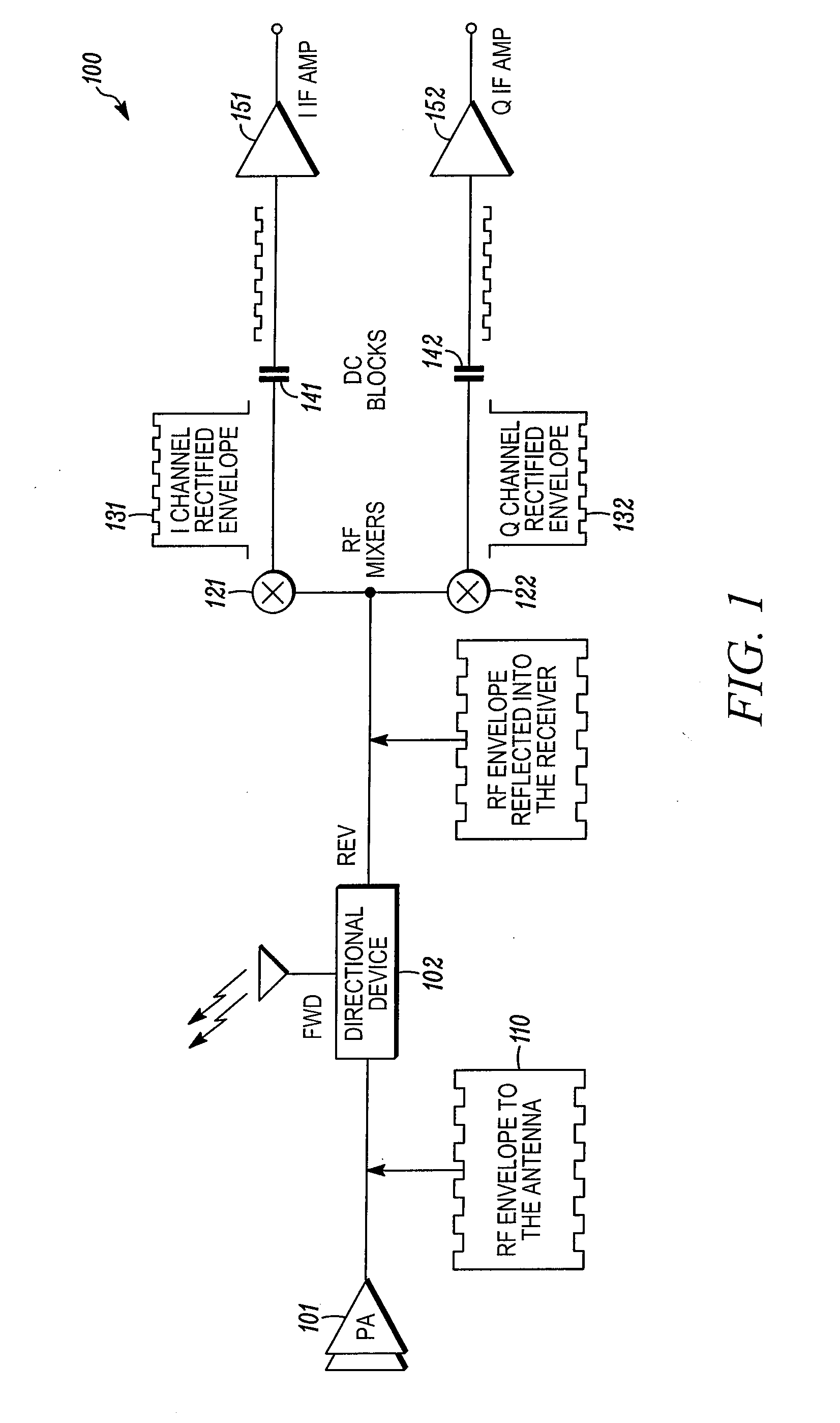
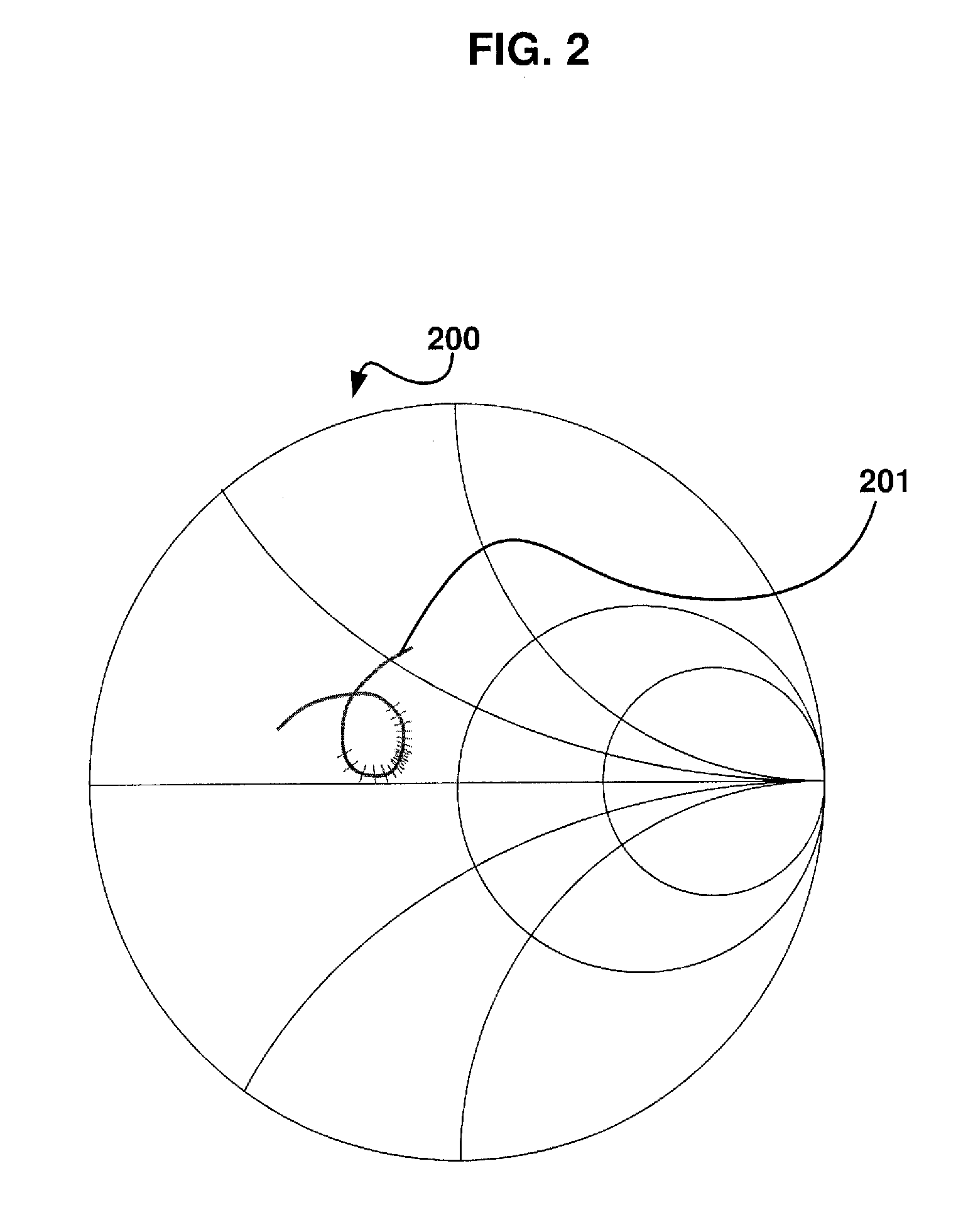
[0004]The present invention is generally related to methods and systems for characterizing an attached antenna to an electronic device, such as a radio frequency identification (“RFID”) reader. One exemplary embodiment is related to a method comprising outputting a low amplitude modulation (“AM”) index radio frequency (“RF”) waveform, the waveform simulating tag data timing and bandwidth, removing a direct current (“DC”) component from the waveform to create a chopped portion of the waveform, applying at least one vector analyzer technique on the chopped portion of the waveform, characterizing at least one antenna impedance vector of the waveform.
[0005]A further exemplary embodiment is related to a communication device comprising an RF source outputting a low AM modulation index RF waveform, the waveform s

Problems solved by technology

The disadvantage is that the reader transmission frequency and the reader reception frequency are essentially identical.
Without that degree of isolation the receiver will be overloaded by the presence of the co-located transmitter signal.
The presence of overloading would create receiver desensitization and intermodulation distortion.

Method used


Image

  • Method and System for Chopped Antenna Impedance Measurements with an RFID Radio
  • Method and System for Chopped Antenna Impedance Measurements with an RFID Radio
  • Method and System for Chopped Antenna Impedance Measurements with an RFID Radio

Examples


Embodiment Construction

[0010]The exemplary embodiments of the present invention may be further understood with reference to the following description of exemplary embodiments and the related appended drawings, wherein like elements are provided with the same reference numerals. The present application generally relates to systems and methods for characterizing an attached antenna to an electronic device, such as a radio frequency identification (“RFID”) reader. Specifically, the exemplary system and methods may measure antenna impedance vectors in order to allow the antenna to be characterized while embedded to the electronic device.

[0011]A Brief Description of a Passive RFID Tag Operation, and the Justification for a Chopped Antenna Impedance Measurement System

[0012]The information that is contained within an RFID passive tag is read out by the use of an RFID reader. The reader functions by first transmitting an RF signal that is intercepted by the antenna on the RFID tag. The intercepted RF signal is re...


PUM


Abstract

Described herein are methods, devices and systems for characterizing an attached antenna to an electronic device, such as a radio frequency identification (“RFID”) reader. One exemplary embodiment is related to a method comprising outputting a low amplitude modulation (“AM”) index radio frequency (“RF”) waveform, the waveform simulating tag data timing and bandwidth, removing a direct current (“DC”) component from the waveform to create a chopped portion of the waveform, applying at least one vector analyzer technique on the chopped portion of the waveform, characterizing at least one antenna impedance vector of the waveform.

Description

FIELD OF THE INVENTION[0001]The present application generally relates to systems and methods for characterizing an attached antenna to an electronic device, such as a radio frequency identification (“RFID”) reader. Specifically, the exemplary system and methods may measure antenna impedance match vectors in order to allow the antenna to be characterized while embedded within the electronic device.BACKGROUND[0002]RFID technology includes systems and methods for non-contact reading of targets (e.g., products, people, vehicles, livestock, etc.) in order to facilitate effective management of these targets within a business enterprise. Specifically, RFID technology allows for the automatic identification of targets, storing target location data, and remotely retrieving target data through the use of RFID tags, or transponders. The RFID tags are an improvement over standard bar codes since the tags may have read and write capabilities. Accordingly, the target data stored on RFID tags can ...

Claims


Application Information

Patent Timeline
IPC IPC(8): H04B17/00
CPCG01R27/04G01R29/10G01R31/2822
Inventor DURON, MARKCONNOLLY, SEANSTRZELCZYK, MARTIN
Owner SYMBOL TECH LLC
Learn More