Image forming method
a technology of forming method and fixing device, which is applied in the direction of electrographic process, electrographic apparatus, instruments, etc., can solve the problems of paper jam or paper wraparound in the fixing device, the gloss difference between the direction of the stripe pattern
- Summary
- Abstract
- Description
- Claims
- Application Information
AI Technical Summary
Benefits of technology
Problems solved by technology
Method used
Image

Examples
embodiment 1
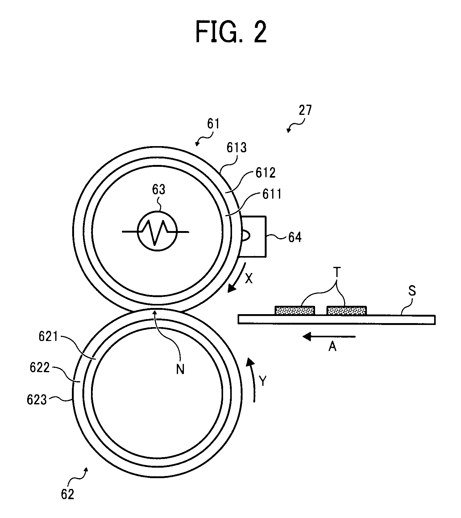
[0045]FIG. 2 is an end-on, axial view schematically illustrating one embodiment of the fixing device 27 incorporated in the image forming apparatus 1.
[0046]As shown in FIG. 2, in the present embodiment of the fixing device 27, the first fixing member comprises a fuser roller 61 extending along a longitudinal axis thereof, and the second fixing member comprises a pressure roller 62 extending along a longitudinal axis thereof. The fuser roller 61 and the pressure roller 62 can rotate around their respective longitudinal axes, while contacting each other with the longitudinal axes generally parallel to form a fixing nip N therebetween.
[0047]The fuser roller 61 is formed of a hollow, cylindrical metal core 611 covered by a layer of elastic material 612 with a coating of release agent 613 applied to an outer surface of the elastic layer 612. The fuser roller 61 has a heat source such as a lamp heater 63 extending along the longitudinal axis to heat the roller body from within, as well as...
embodiment 2
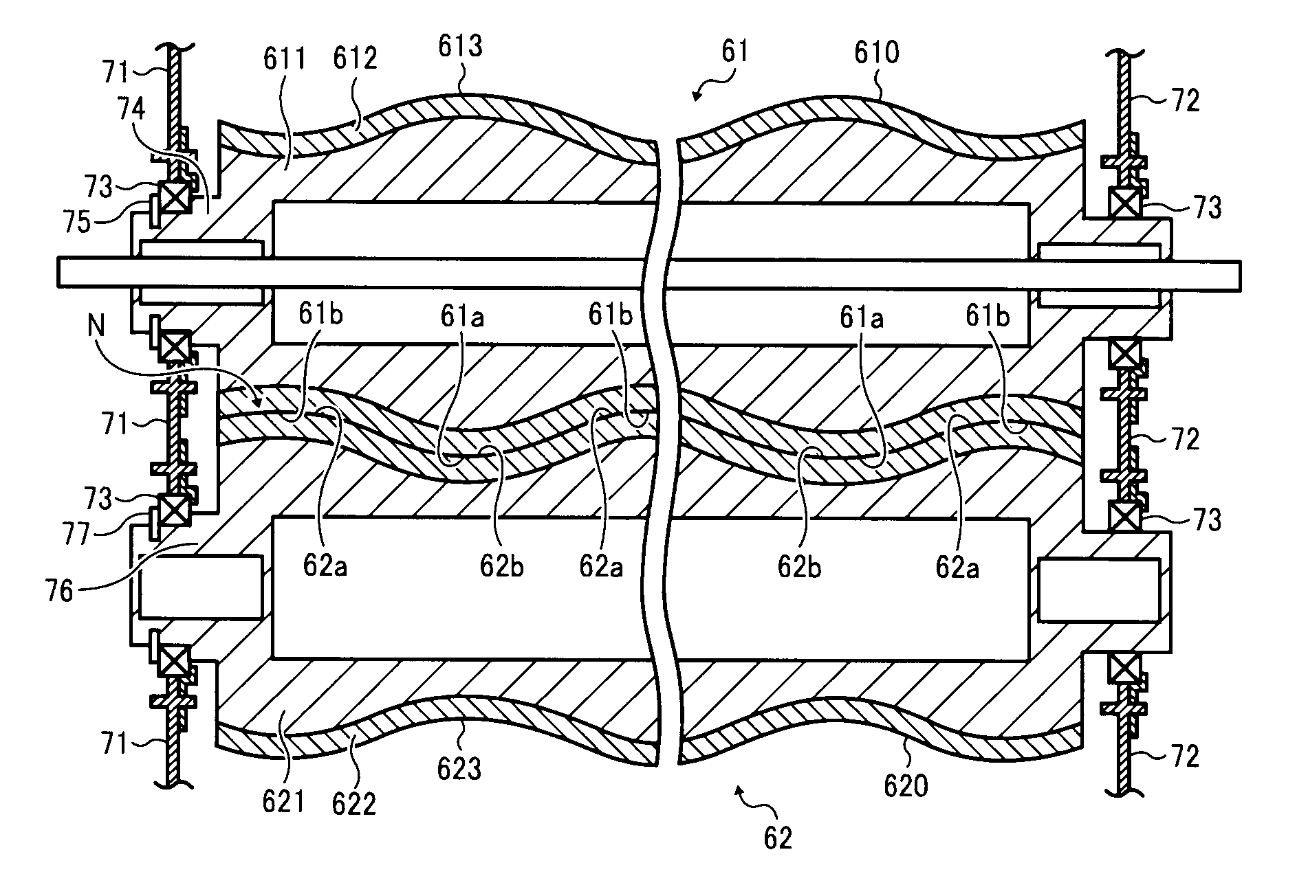
[0086]FIG. 7 shows another embodiment of the fuser roller 61 and the pressure roller 62 mounted in the fixing device 27.
[0087]As shown in FIG. 7, the present embodiment is similar to that depicted in FIG. 5, except that the convex and concave portions 61a and 61b of the fuser roller 61 are formed by varying the thickness of the elastic layer 612, with the metal core 611 and the release coating 613 each having a substantially uniform thickness or cross-section along the longitudinal axis, and the convex and concave portions 62a and 62b of the pressure roller 62 are formed by varying the thickness of the elastic layer 622, with the metal core 621 and the release coating 623 each having a substantially uniform thickness or cross-section along the longitudinal axis.
[0088]Except for the thickness variation in the elastic layers 612 and 622 and the uniform thickness of the metal cores 611 and 621, the embodiment depicted in FIG. 7 includes features identical to those depicted in the embod...
embodiment 3
[0090]In further embodiments, the undulating fixing rollers 61 and 62 may have other configurations than that depicted in FIGS. 3 to 7, wherein each roller has convex and / or concave portions that are partially straight, i.e., exhibiting substantially no curvature, in the axial direction. FIGS. 8 and 9 show examples of such configurations.
[0091]As shown in FIG. 8, the convex portion 61a of the fuser roller 61 may have a flat apex 61c that has a profile parallel to the longitudinal axis of the roller 61 and exhibits substantially no curvature in the axial direction, and the concave portion 62b of the pressure roller 62 may have a flat apex 62c that has a profile parallel to the longitudinal axis of the roller 62 and exhibits substantially no curvature in the axial direction. The flat portions 61c and 62c are formed without sharp edges or corners on their perimeters, so that the undulating surfaces 61 and 62 are generally smooth and continuous across the fixing nip N.
[0092]Alternativel...
PUM
| Property | Measurement | Unit |
|---|---|---|
| Time | aaaaa | aaaaa |
| Percent by mass | aaaaa | aaaaa |
| Percent by mass | aaaaa | aaaaa |
Abstract
Description
Claims
Application Information
 - R&D
- Intellectual Property
- Life Sciences
- Materials
- Tech Scout
- Unparalleled Data Quality
- Higher Quality Content
- 60% Fewer Hallucinations
Browse by: Latest US Patents, China's latest patents, Technical Efficacy Thesaurus, Application Domain, Technology Topic, Popular Technical Reports.
© 2025 PatSnap. All rights reserved.Legal|Privacy policy|Modern Slavery Act Transparency Statement|Sitemap|About US| Contact US: help@patsnap.com