
Drawworks device on a drill floor

Active Publication Date: 2010-11-25
NAT OILWELL VARCO NORMAY AS
View PDF8 Cites 8 Cited by
  • Summary
  • Abstract
  • Description
  • Claims
  • Application Information

AI Technical Summary

Benefits of technology

[0010]The invention has for its object to remedy or r

Problems solved by technology

However, experience went to show that the main block, which is of considerable dimensions, was obstructive to the work on the drill floor when oriented with the pulley axis in said direction.
However, when, in its position laterally offset, the main block is hoisted towards its upper position, there is in this more recent construction an unfavourable wire angle between the hoisting wire and the wire pulleys of the upper pulley assembly.
This unfavourable wire angle leads to unnecessarily great wear to the pulleys of the upper pulley assembly and to the wire.

Method used


Image

  • Drawworks device on a drill floor
  • Drawworks device on a drill floor
  • Drawworks device on a drill floor

Examples


Embodiment Construction

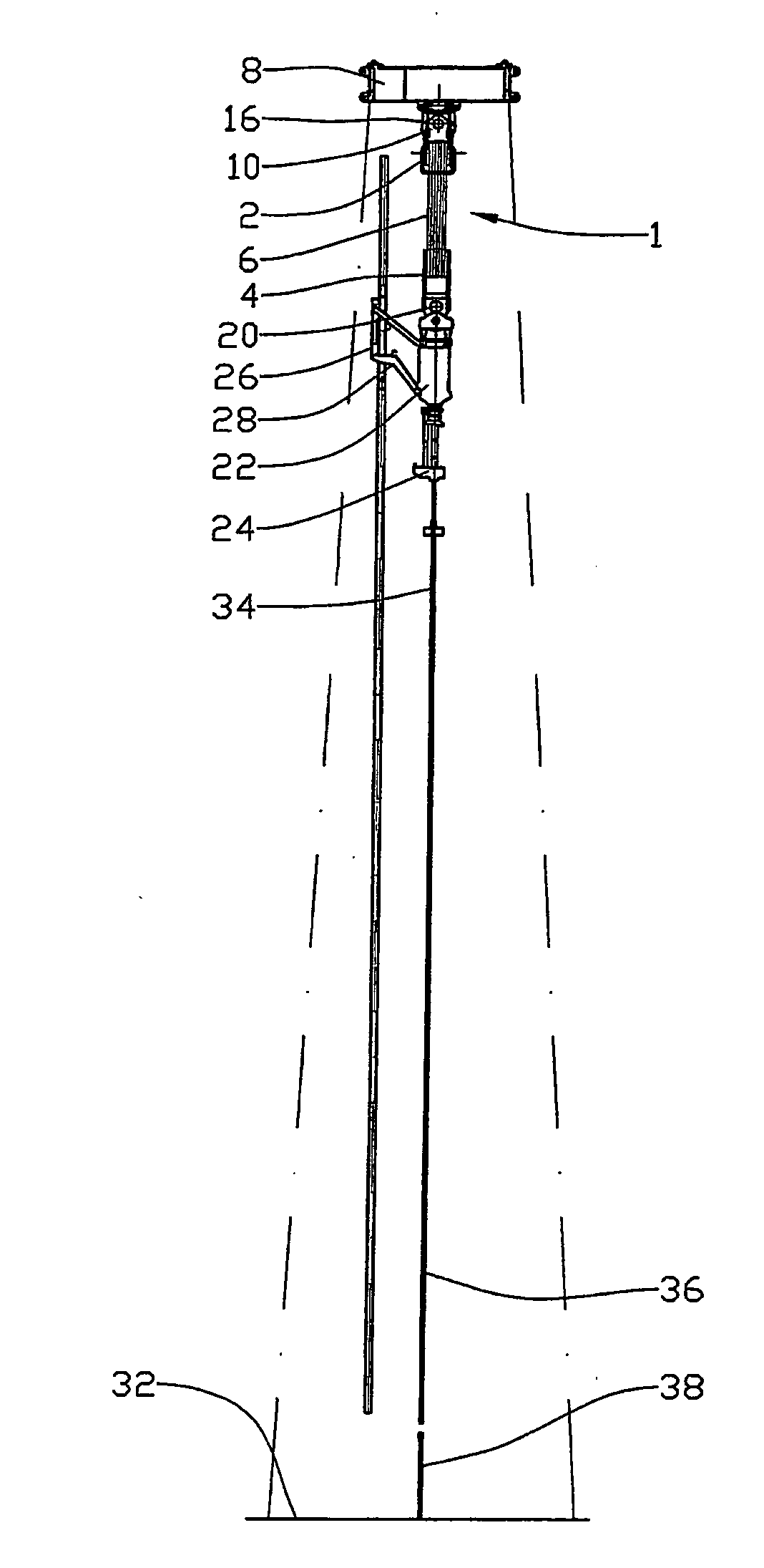
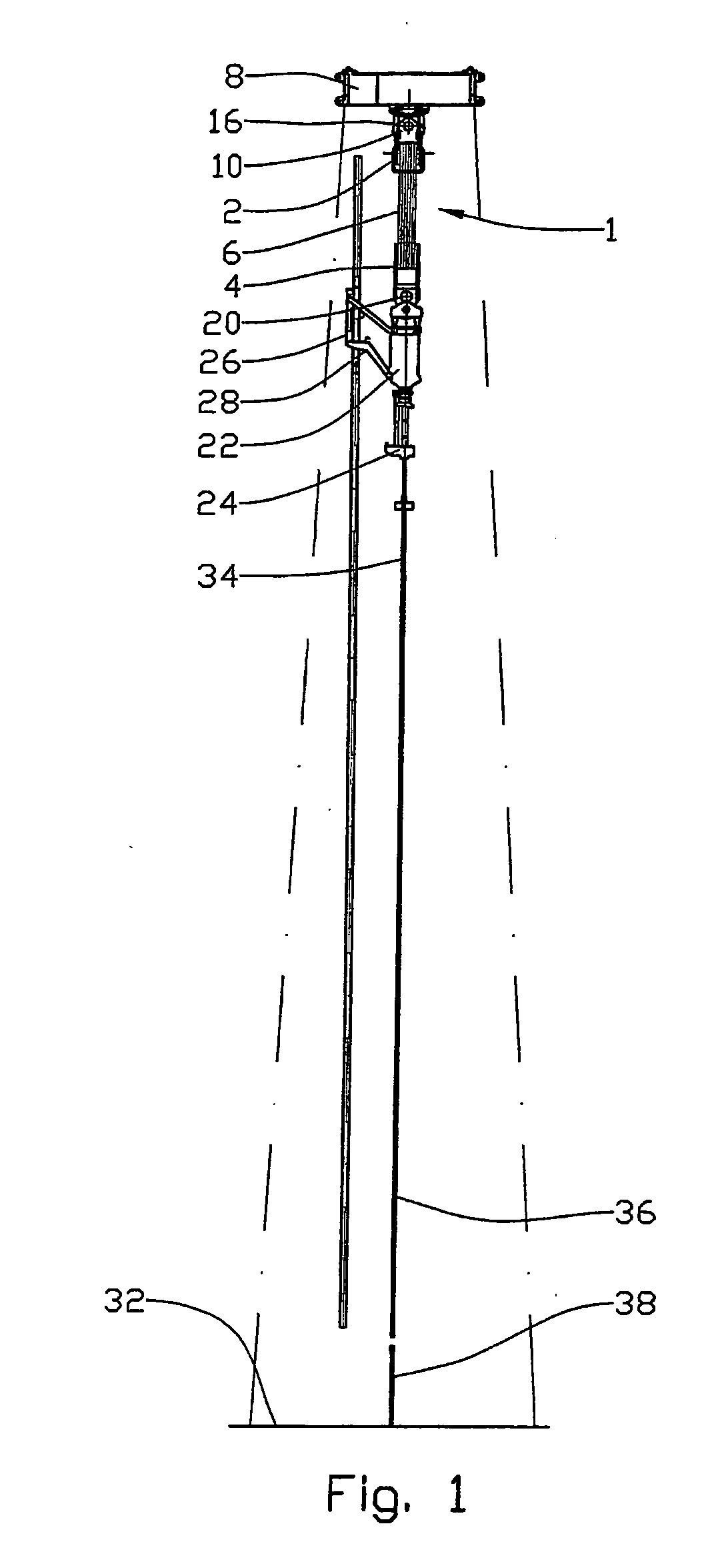
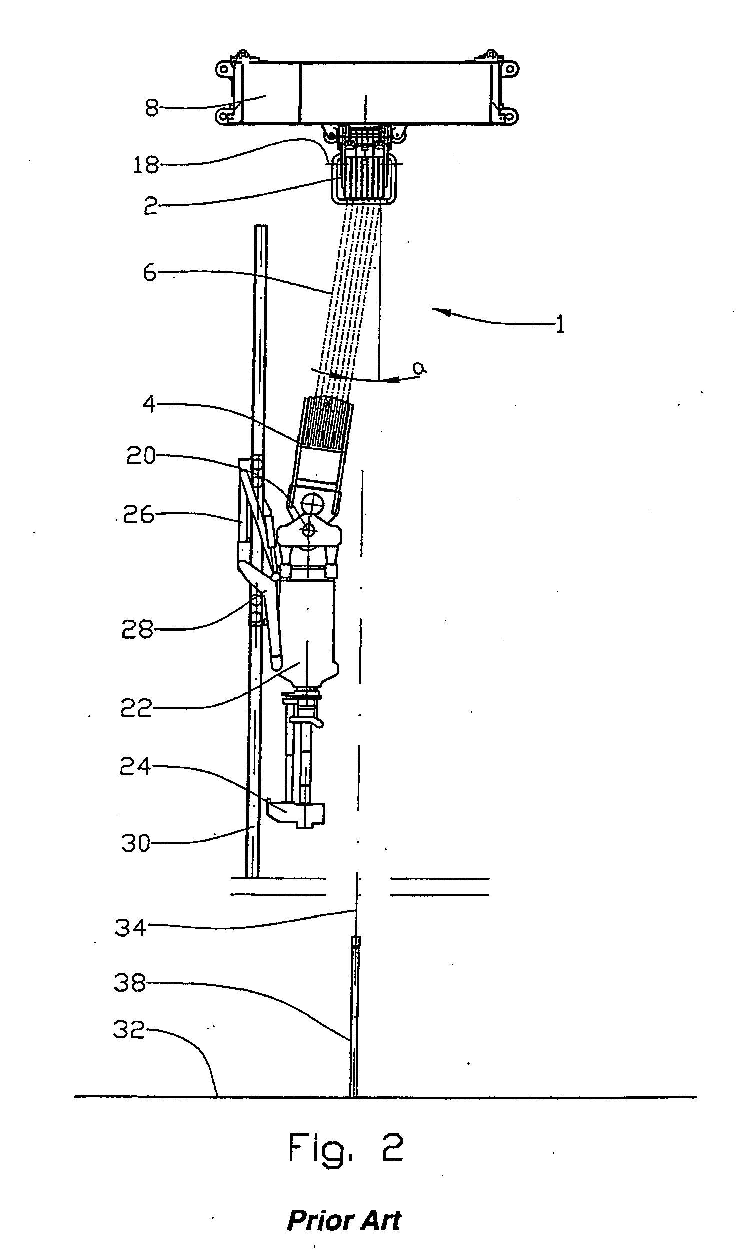
[0020]In the drawings the reference numeral 1 indicates a drawworks including, apart from a winch not shown, an upper pulley assembly 2, a main block 4 and a hoisting wire 6.

[0021]The upper pulley assembly 2 is connected to a mounting 8 in the form of a crown beam by means of a hinged adapter 10.

[0022]The hinged adapter 10 includes an upper portion 12 which is connected to the crown beam 8, and a lower portion 14 which is connected to the pulley assembly, see FIG. 4, the upper portion 12 and the lower portion 14 hinging relative to each other about a first axis 16.

[0023]The first axis 16 is approximately perpendicular to the direction of lateral movement of the main block 4.

[0024]The main block 4 is connected about a second axis 20 to a drilling machine 22 including a pipe mount 24. The second axis 20 is parallel to the first axis 16.

[0025]The drilling machine 22 is connected, in a manner known per se, to a carriage 26 by means of pivotal arms 28. The carriage 26 is movable along a ...


PUM


Abstract

A drawworks device on a drill floor which includes an upper pulley assembly) connected to a heave-compensated or fixed mounting, and a main block connected to a pipe mount which is laterally movable in at least one direction relative to the drilling centre of the drill floor, the pulley assembly pivotal about a horizontal first axis which is perpendicular to the direction of lateral movement.

Description

CROSS REFERENCE TO RELATED APPLICATIONS[0001]This application claims the benefits of priority under the Patent Laws of the United States of Norway Application Number 20062853 filed Jun. 19, 2006; and International Application Number PCT / NO2007 / 000195 filed Jun. 7, 2007 published as International Publication Number WO 2007 / 148977 A1 on Dec. 27, 2007—all of which applications and publication are incorporated fully herein for all purposes.BACKGROUND OF THE INVENTION[0002]1. Field of the Invention[0003]This invention relates to a drawworks. More particularly it relates to a drawworks on a drill floor, the drawworks including an upper pulley assembly connected to a heave-compensated or fixed mounting, and a main block connected to a pipe mount which is laterally movable relative to the drilling centre of the drill floor in at least one direction, the pulley assembly being rotatable about a horizontal first axis perpendicular to the direction of lateral movement.[0004]2. Description of Re...

Claims


Application Information

Patent Timeline
IPC IPC(8): B66D1/60E21B19/02E21B19/084E21B3/02E21B7/00
CPCE21B19/02
Inventor TARALDRUD, PAAL
Owner NAT OILWELL VARCO NORMAY AS
Learn More