
Stereo camera apparatus and vehicle-mountable monitoring apparatus using same

a camera and stereo technology, applied in the direction of image enhancement, instruments, transportation and packaging, etc., can solve the problems of not being able to detect too-close objects at distances such as 20 m or less ahead, requiring a larger number of optical components, and reducing the safety of both drivers and passengers

Inactive Publication Date: 2010-11-11
RICOH KK
View PDF6 Cites 72 Cited by
  • Summary
  • Abstract
  • Description
  • Claims
  • Application Information

AI Technical Summary

Benefits of technology

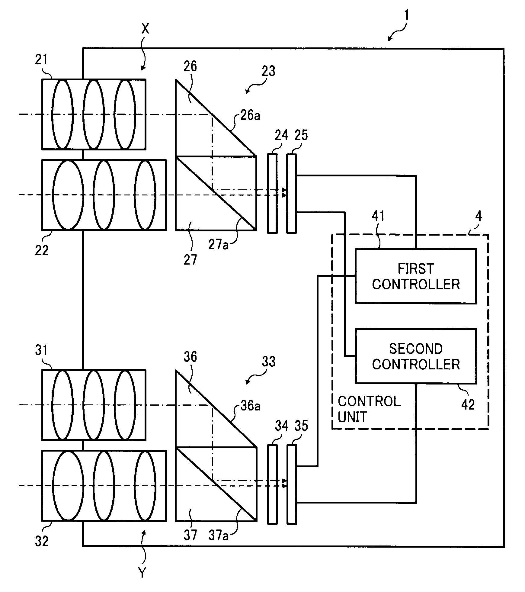
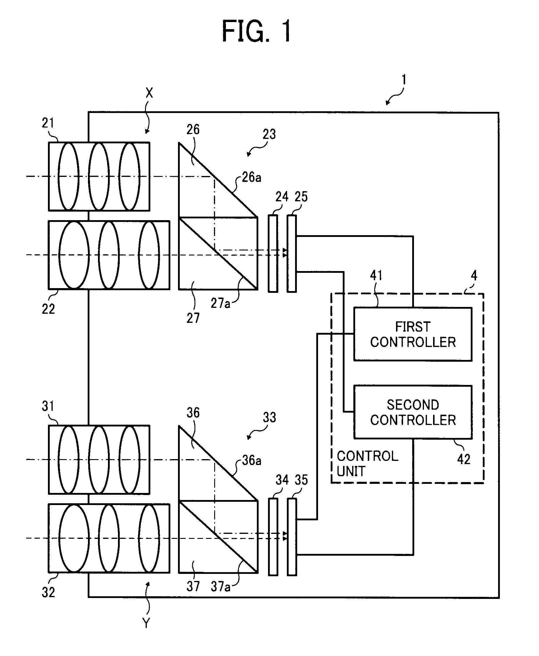
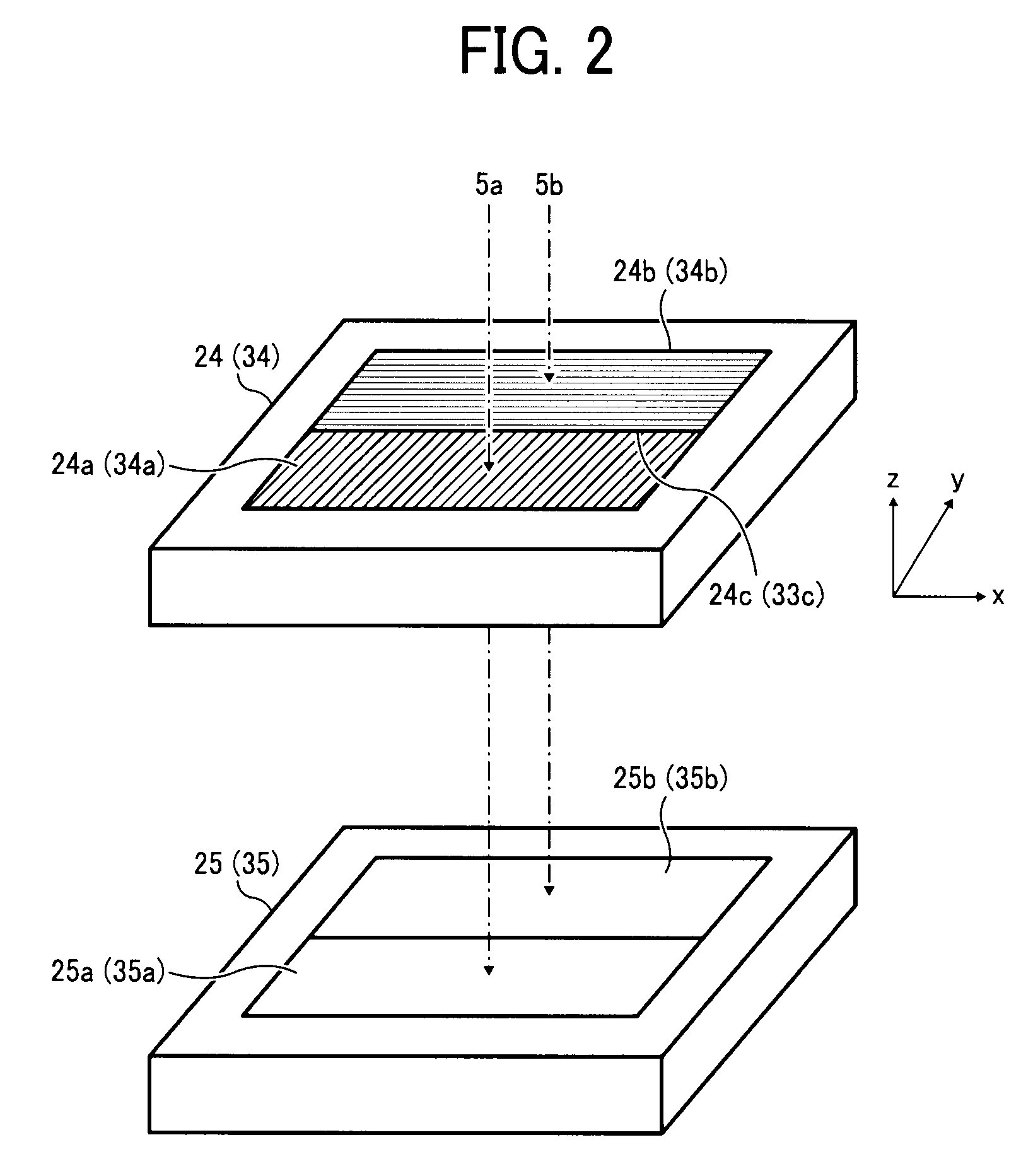
The present invention relates to a stereo camera apparatus that includes two image capturing units to capture images of an object from different angles. The first unit captures an image of the object using a first lens unit and a first light synthesis unit, while the second unit captures an image of the object using a second lens unit and a second light synthesis unit. The first and second units are controlled by a control unit to process the captured images. The first and second lens units have different focal lengths, and the first light synthesis unit reflects light coming from the first lens unit to guide a S-polarized light component of the light to the first area-divided filter, which separates the light into S-polarized and P-polarized light components. The first image capturing element receives the S-polarized and P-polarized light components to detect a S-polarized light component image and a P-polarized light component image. The second image capturing unit includes a third lens unit and a fourth lens unit to capture the S-polarized and P-polarized light components. The control unit controls the first and second units to process the captured images. The technical effect of the invention is to provide a stereo camera apparatus that can capture images of an object from different angles and detect the position of the object using the S-polarized and P-polarized light components.

Problems solved by technology

The stereo cameras for long-range can detect far objects such as 100 m ahead of the vehicle, but cannot detect too-close objects at distances such as 20 m or less ahead of the vehicle.
A big stereo camera mounted at such rear-view mirror position may oppress the driver and / or the passenger and can pose a safety risk for both driver and passenger.
However, such a configuration requires a greater number of parts for the optical systems.
For example, the number of lenses and image capturing elements may be twice or more that of ordinary stereo cameras, by which manufacturing cost of the vehicle-mountable monitoring apparatuses may increase.
However, due to the principle of triangulation, a shorter baseline length may hinder a distance measurement for far objects.

Method used


Image

  • Stereo camera apparatus and vehicle-mountable monitoring apparatus using same
  • Stereo camera apparatus and vehicle-mountable monitoring apparatus using same
  • Stereo camera apparatus and vehicle-mountable monitoring apparatus using same

Examples


Embodiment Construction

[0037]A description is now given of exemplary embodiments of the present invention. It should be noted that although such terms as first, second, etc. may be used herein to describe various elements, components, regions, layers and / or sections, it should be understood that such elements, components, regions, layers and / or sections are not limited thereby because such terms are relative, that is, used only to distinguish one element, component, region, layer or section from another region, layer or section. Thus, for example, a first element, component, region, layer or section discussed below could be termed a second element, component, region, layer or section without departing from the teachings of the present invention.

[0038]In addition, it should be noted that the terminology used herein is for the purpose of describing particular embodiments only and is not intended to be limiting of the present invention. Thus, for example, as used herein, the singular forms “a”, “an” and “the...


PUM


Abstract

A stereo camera apparatus includes first and second image capturing units and a control unit. The first image capturing unit includes first and second lens units, a first light synthesis unit, a first area-divided filter, and a first image capturing element. The first light synthesis unit and the first area-divided filter guide S-polarized and P-polarized light components to the first image capturing element to detect S-polarized and P-polarized light component images. The second image capturing unit includes third and fourth lens units, a second light synthesis unit, a second area-divided filter, and a second image capturing element. The second light synthesis unit and the second area-divided filter guide S-polarized and P-polarized light components to the second image capturing element to detect S-polarized and P-polarized light component images. The control unit includes first and second controllers to compute three-dimensional data of object using the S-polarized and P-polarized light component images, respectively.

Description

CROSS-REFERENCE TO RELATED APPLICATIONS[0001]This application claims priority to Japanese Patent Application No. 2009-114153, filed on May 11, 2009 in the Japan Patent Office, which is hereby incorporated by reference herein in its entirety.BACKGROUND OF THE INVENTION[0002]1. Field of the Invention[0003]The present invention relates to a stereo camera apparatus and a vehicle-mountable monitoring apparatus using the stereo camera apparatus, and more particularly, to a compact stereo camera apparatus of reduced size that can enhance measurable distance range and angle of view.[0004]2. Description of the Background Art[0005]More and more vehicles such as automobiles have been equipped with safety devices to enhance vehicle safety. For example, a forward-watching device, such as a television camera or a laser-equipped radar unit, may be mounted on a vehicle to detect vehicles and / or obstructions or objects in front of the vehicle. The information gained by such detection can be used to ...

Claims


Application Information

Patent Timeline
Patent Type & Authority Applications(United States)
IPC IPC(8): H04N13/02G02B30/25
CPCG06T7/0075G06T2207/10012H04N13/0239G02B1/005G02B5/3041B60R2300/107G02B27/283G03B35/08H04N13/0242H04N13/0296B60R1/00G02B27/1066G06T7/593H04N13/243H04N13/296H04N13/239B60R1/24B60R1/31
Inventor OOHCHIDA, SHIGERUAOKI, SHINFUJIMOTO, MASAHIROHIRAI, HIDEAKIYAMADA, YASUFUMIMORITA, NOBUHIRO
Owner RICOH KK
Learn More