
Integrated graphical containment structure

a containment structure and graphic technology, applied in the direction of flexible pipes, pipes, electrical equipment, etc., can solve the problems of cumbersome and unattractive temporary containment of these conduits, and achieve the effect of simple and economical

Inactive Publication Date: 2010-11-11
SOLUTION FINDERS
View PDF16 Cites 7 Cited by
  • Summary
  • Abstract
  • Description
  • Claims
  • Application Information

AI Technical Summary

Benefits of technology

This patent is about a protective cover for service cords and utilities that are routed across floors, walls, and ceilings in unorganized fashion. The cover is made of a one-piece, transparent plastic member that includes channels to receive the service elements and is designed to be easily attached to a supporting surface. The cover can be offered in several variations and is intended to complement its surrounding environment. The technical effect of this invention is to provide a simple and economical solution to temporarily route and manage service cords and utilities in both commercial and residential applications.

Problems solved by technology

Temporary containment of these conduits is cumbersome and unattractive.

Method used


Image

  • Integrated graphical containment structure
  • Integrated graphical containment structure
  • Integrated graphical containment structure

Examples


Embodiment Construction

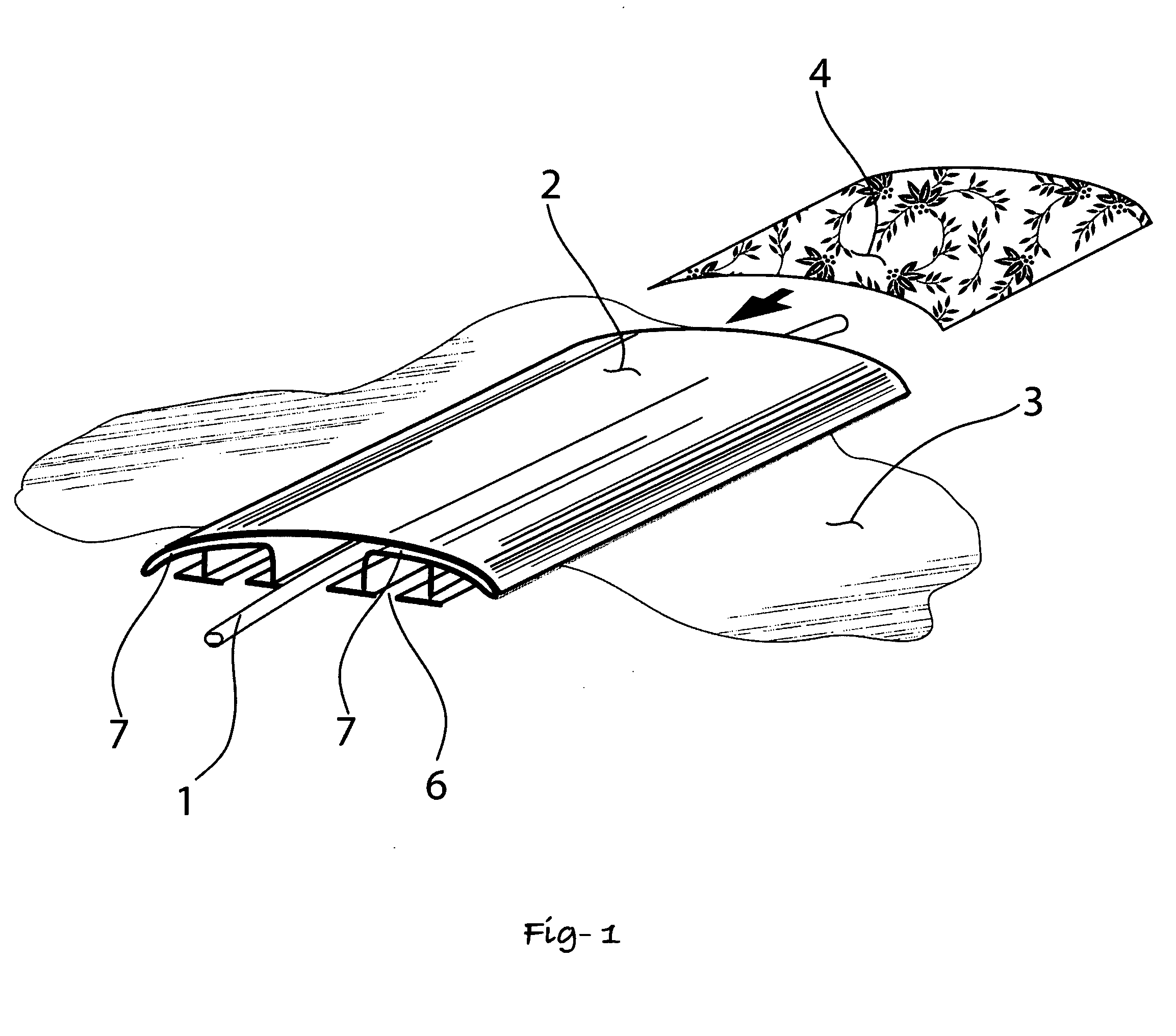
[0023]The illustration in FIG. 1 depicts a service cord or utility 1 in close proximity with surface 3. The service cord or utility 1 represents power, data, and communication, pneumatic, vacuum, or hydraulic services. The containment structure 2 includes a recess 7 to accept a graphical insert 4 to compliment its proximity with surface 3. Surface 3 could be a wall, ceiling, floor, desk, table, or any other planer mounting surface.

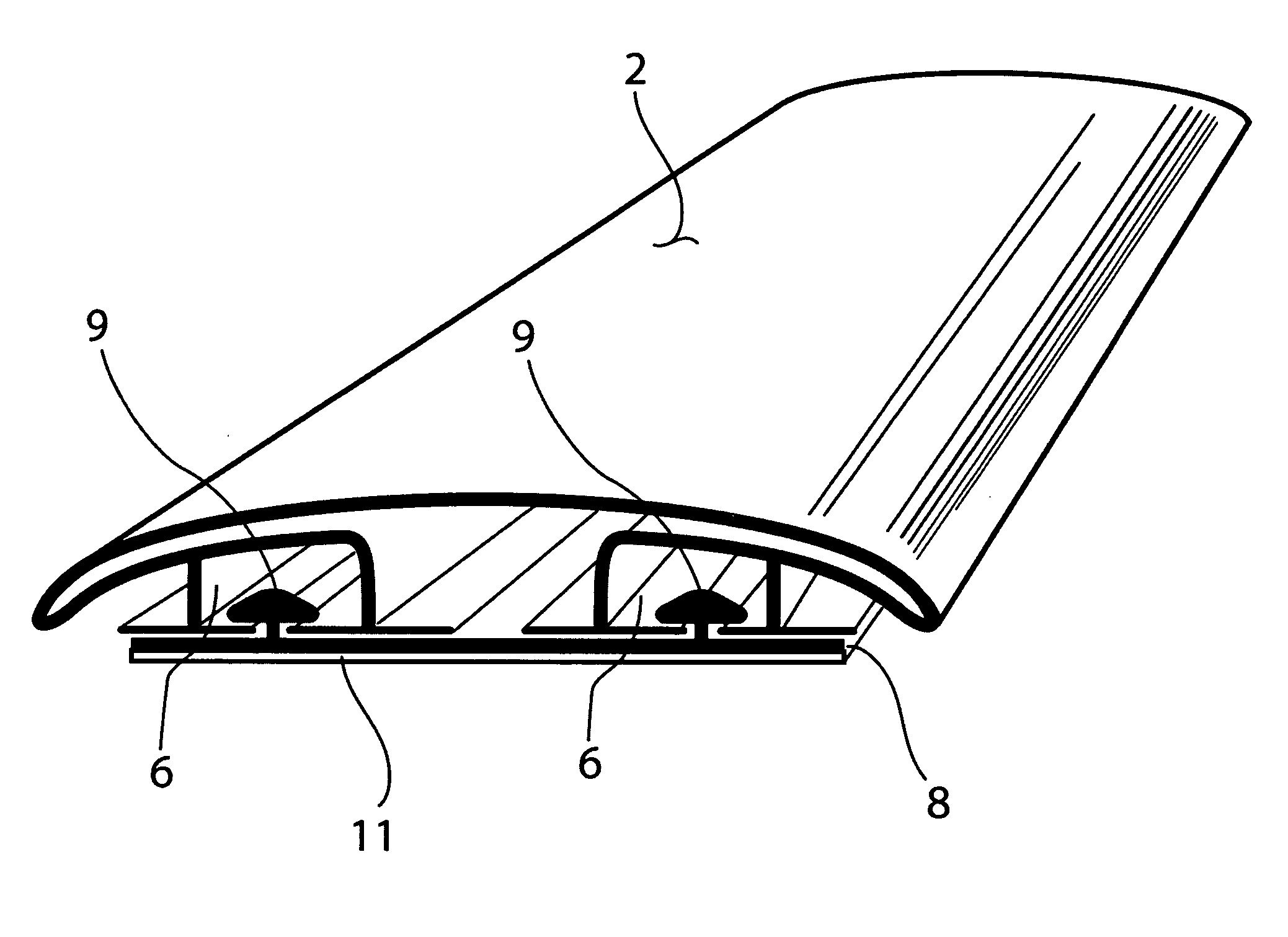
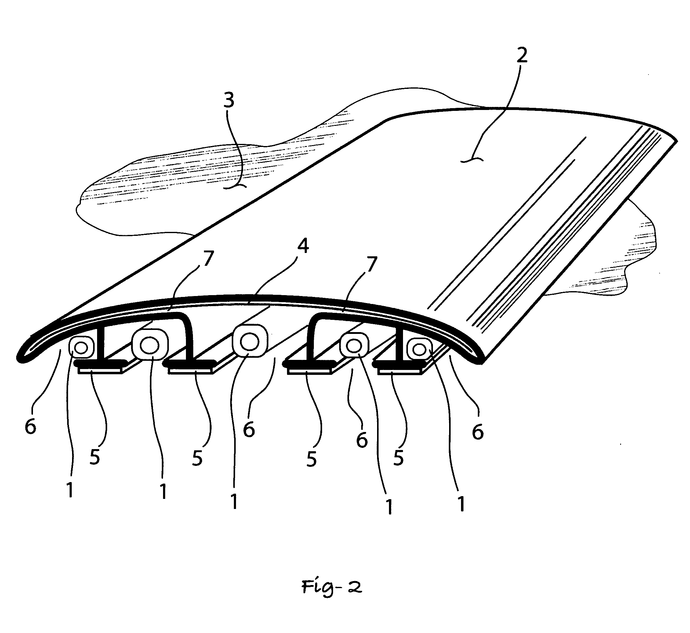
[0024]The sectional view shown in FIG. 2 illustrates various features of the invention. A clear, transparent, or opaque containment structure 2 includes features to route service cords or utilities 1 and a recess 7 spanning the upper surface to retain a graphical insert 4. The graphical insert 4 is designed to visually contrast, camouflage, or complement with surface 3. Multiple channels 6 within the containment structure 2 allow routing service cords or utilities 1. A non-slip material 5 prevents the containment structure 2 from sliding or moving with res...


PUM


Abstract

A clear plastic member is formed to provide channels to contain service cords and utilities. The center channel most generally will contain the power cord. The channels on each side of the center channel are of smaller cross section and may include data, communication, and utility applications in any combination. Central and part of the extruded member is a cavity that transverses the entire top area of the member. The application of this cavity is to encapsulate a pattern representative of the floor, wall, veiling, or desk that the device is being mounted to, or this cavity could also contain graphical details including the logo of the company, legends, and other customized details to provide complimentary graphical details with the power, communication, data, or utility services.

Description

CROSS REFERENCE TO RELATED APPLICATIONS[0001]This application claims priority from U.S. Provisional Application Ser. No. 61 / 215,762, filed May 8, 2009, the disclosure of which is incorporated herein in its entirety by reference.FEDERALLY SPONSORED RESEARCH AND DEVELOPMENT[0002]This application contains no federal sponsored research or development.BACKGROUND OF THE INVENTION[0003]The objective of the invention is to provide a method to route and graphically complement service cords and utility services transferred across, a floor, ceiling, wall or desk. The service cords can include power, data, and communication applications. Additionally, utility services such as hydraulic, pneumatic, and vacuum services are included.[0004]Both residential and commercial applications exist for this device. In a residence, the routing of a table lamp cord across carpet, tile or a wood floor is an example of an application which requires both mechanical protection and blending with the mating surface...

Claims


Application Information

Patent Timeline
Patent Type & Authority Applications(United States)
IPC IPC(8): F16L55/00
CPCH02G2200/20H02G9/025
Inventor MAUE, H. WINSTONKEMPF, JEFF A.TAHNOOSE, TERRI L.GROSSMAN, ASSI
Owner SOLUTION FINDERS
Learn More