
Arrangement for weapon

a weapon and barrel technology, applied in the direction of weapons, missile propulsion, firing/trigger mechanisms, etc., can solve the problems of a large risk behind the weapon, a large shear force on the barrel towards the outlet, etc., and achieve the effect of improving the symmetrical opening operation and facilitating the recoil

Inactive Publication Date: 2010-11-11
SAAB AB
View PDF5 Cites 8 Cited by
  • Summary
  • Abstract
  • Description
  • Claims
  • Application Information

AI Technical Summary

Benefits of technology

[0007]One object of the present invention is to provide an arrangement for a weapon with a countermass container, which brings about an improved symmetrical opening operation with favourable recoil in a better way than before.
[0012]This in turn results in as small a variation spread as possible in the opening operation of the bottom and the best opportunity for small recoil spreads has thus been created.
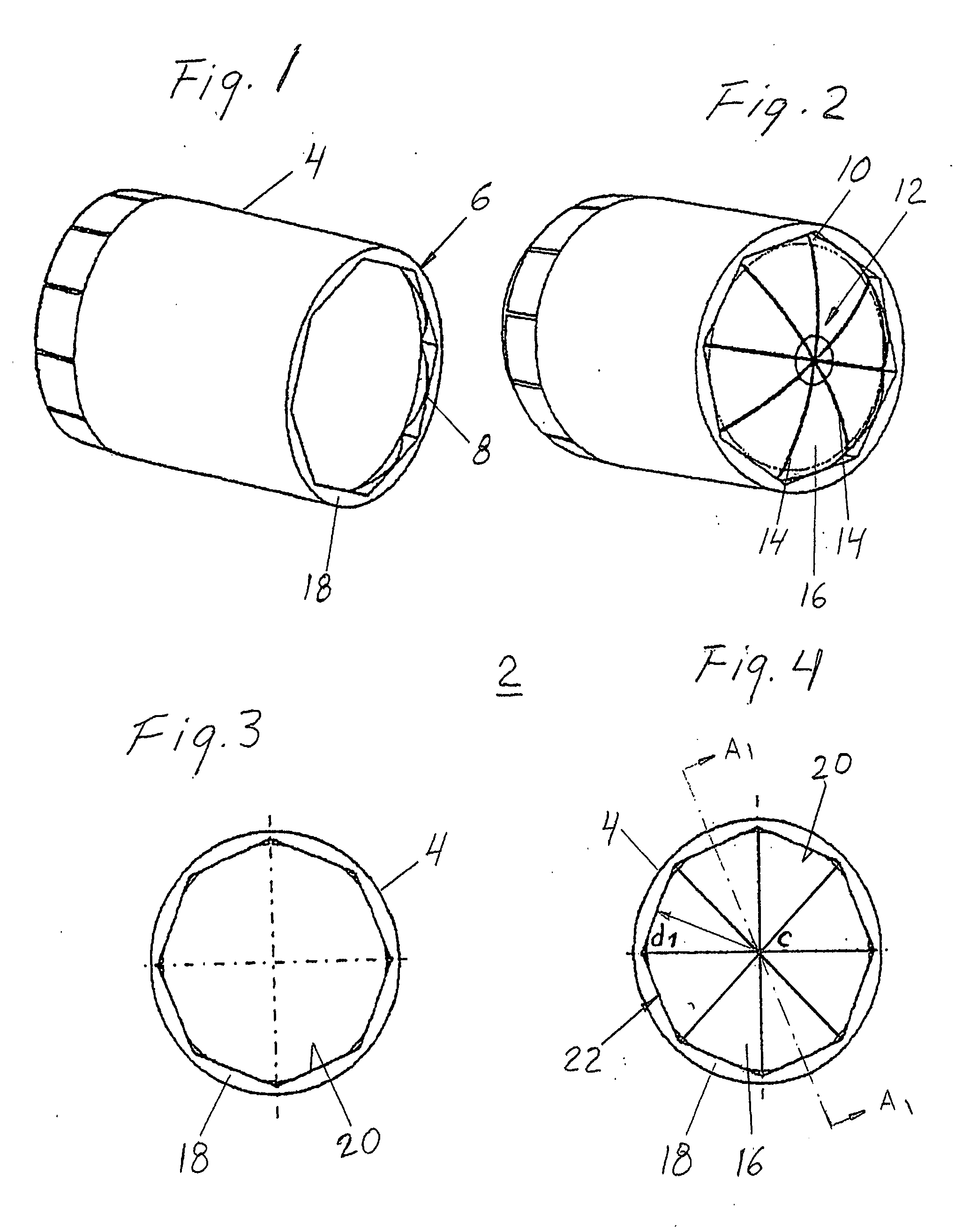
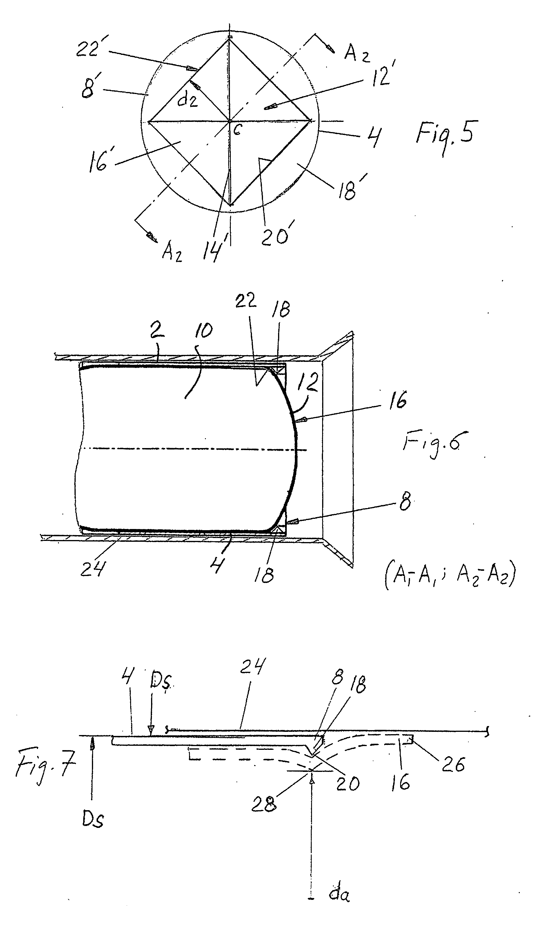
[0013]Further, it results in a reproducible, almost identical opening area, even if different weapons are utilized. Moreover, this makes it possible to restrict the generation of undesirable forces which might exert negative influence on the weapon, control the recoil progress and minimize the risk of an asymmetric pressurising of the countermass, each of which would affect the alignment of the weapon during the period when the shell is moving forward in the barrel. In addition, by varying the number of flaps and corresponding support members it is possible to control the opening are in the bottom of the container. Advantageously, each openable flap might be triangular and in the open state configured with free equilateral legs and a base region integral with the wall of the countermass container.

Problems solved by technology

If any part of the bottom does not open at the same time as the other parts, an asymmetric flow is created when the countermass is leaving the countermass container, which can produce great shear forces on the barrel towards the outlet.
In case the bottom would fall apart into pieces, these would constitute a great risk behind the weapon.

Method used


Image

  • Arrangement for weapon
  • Arrangement for weapon
  • Arrangement for weapon

Examples


Embodiment Construction

[0022]The general principles of an arrangement for a weapon comprising a countermass container mentioned by way of introduction and particularly solutions to obtain symmetrical opening of the cover of the countermass container are described in our SE patents 0301626-8 and 0301627-6 and therefore not described in greater detail here. The subject matter of the present invention is related to the opening of the bottom section of the counter mass container.

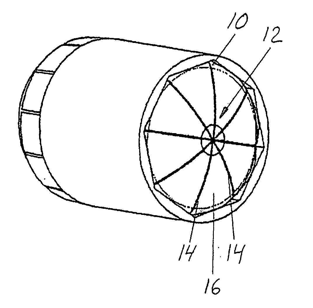
[0023]FIG. 1 is a perspective view of an arrangement 2 for a weapon with countermass container comprising a sleeve 4, in one end of which a guiding folding support 6 is configured by means of an annular element 8. In this embodiment said sleeve 4 is configured as a lining or casing for the counter mass container, which is mountable in the sleeve 4.

[0024]FIG. 2 is a perspective view of the sleeve in FIG. 1, in which a counter mass container 10 of a conventional kind is mounted. In this embodiment said container is configured with an op...


PUM


Abstract

An arrangement for a weapon including a countermass for reducing the pressure around the weapon. The countermass is enclosed in a container, which is mountable in the barrel of the weapon behind an ammunition part. The container is provided with an openable bottom with break indications. A guiding folding support, configured as an annular element, is arranged adjacent to the openable bottom on the outside of the bottom relative to the countermass container. The annular element is provided with a support member for each openable flap forming part of the bottom. Thereby, the opening area in the bottom of the counter mass container is defined by folding edges, formed in each base region of the flaps in the open state as in contact with its corresponding support member.

Description

BACKGROUND OF THE INVENTION[0001]1. Technical Field of the Invention[0002]The present invention relates to an arrangement for a weapon comprising a countermass for reducing the pressure around the weapon, the countermass being enclosed in a container, which is mountable in the barrel of the weapon behind an ammunition part, such as a projectile or shell, and comprising an openable cover with break indications on the ammunition part side and an openable bottom with break indications on the other side.[0003]2. Description of Related Art[0004]In order to increase the backward momentum and thus make possible an increase in weight of the ammunition part without excessively high pressure being created behind the weapon, it has been known for many years to introduce what is known as a countermass. A critical stage in weapons with countermass is the opening phase of the countermass container. In this connection reference might be made to our SE patents 0301626-8 and 0301627-6, which disclos...

Claims


Application Information

Patent Timeline
Patent Type & Authority Applications(United States)
IPC IPC(8): F41A1/10
CPCF41F3/0455F41A1/10
Inventor AX, LARSLANTZ, EJENORGREN, KENTPETTERSSON, ROLF
Owner SAAB AB
Learn More