
Method, apparatus, and computer program for irrigating a field space wtih a center pivot irrigation machine

a technology of center pivot and irrigation machine, which is applied in the direction of automatic control, process and machine control, instruments, etc., can solve the problem of insufficient choice of leading or lagging auxiliary pipelines

Active Publication Date: 2010-10-28
LINDSAY CORP
View PDF18 Cites 16 Cited by
  • Summary
  • Abstract
  • Description
  • Claims
  • Application Information

AI Technical Summary

Benefits of technology

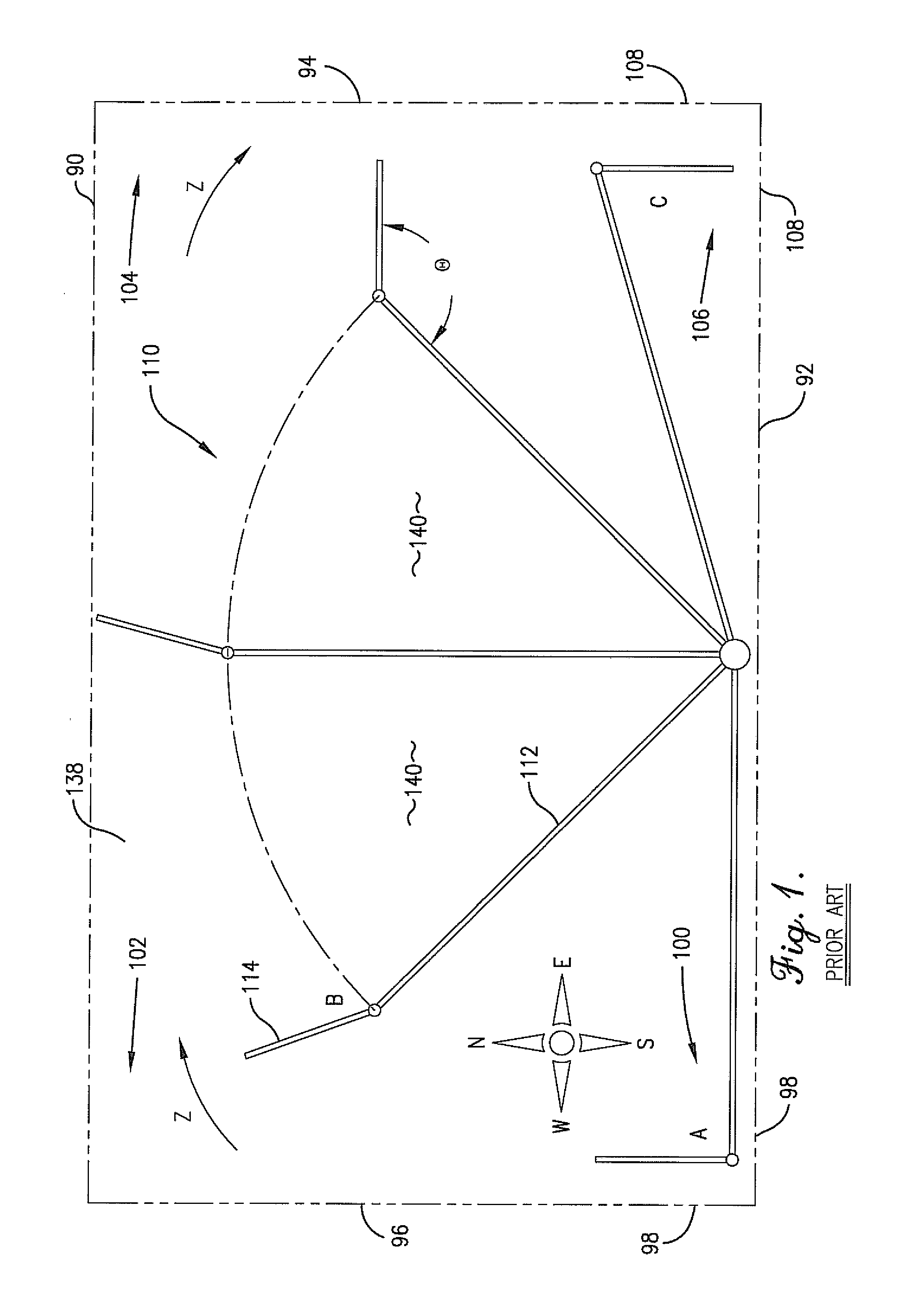
[0004]In prior art center pivot irrigation machines, the auxiliary pipeline is operable to either lead ahead or lag behind the main pipeline, but not both, when the pipeline is rotating through the field space in a single direction. For a field space that allows for the main pipeline to rotate approximately 360°, the ability for the auxiliary pipeline to either lead or lag the main pipeline is usually not problematic. Regardless of whether the auxiliary pipeline is leading or lagging the main pipeline, the auxiliary pipeline is positioned to allow for uniform application coverage of the secondary field space because the main pipeline rotates a full 360° in the field space. However, in field spaces that are either partially circular, i.e., that do not allow for an approximately 360° rotation of the main pipeline in the field space, or that include boundaries or obstructions that do not optimally allow for the auxiliary pipeline to either lead or lag, but not both, the choice of either a leading or a lagging auxiliary pipeline is insufficient. As used herein, a partially circular field space is defined as any field space that does not allow for an approximately 360° rotation of the main pipeline in the field space. Therefore, partially circular field spaces include, for example, field spaces that allow the main pipeline to rotate approximately 90°, 180°, 270°, or even approximately 350°. It is to be expressly understood that embodiments of the present invention can be used for completely circular field spaces, and that such use would be advantageous in those instances where the field space includes boundaries or obstructions that would be optimally accounted for using the present invention.
[0007]The present invention solves the above-described problems and provides a distinct advance in the art of center pivot irrigation machines. More particularly, embodiments of the present invention provide an auxiliary pipeline operable to both lead and lag a main pipeline of a center pivot irrigation machine during progressive rotation of the main pipeline in a single direction through a field space. To accomplish both the leading and lagging with respect to the main pipeline, the auxiliary pipeline is operable to rotate at least approximately 0° and up to 360° with respect to the main pipeline. The only restriction on the minimum and maximum swing angles and within a 0°-360° rotation is a size of trusses mounted on the main and auxiliary pipelines and the prevention of the respective trusses colliding with each other.

Problems solved by technology

However, in field spaces that are either partially circular, i.e., that do not allow for an approximately 360° rotation of the main pipeline in the field space, or that include boundaries or obstructions that do not optimally allow for the auxiliary pipeline to either lead or lag, but not both, the choice of either a leading or a lagging auxiliary pipeline is insufficient.

Method used


Image

  • Method, apparatus, and computer program for irrigating a field space wtih a center pivot irrigation machine
  • Method, apparatus, and computer program for irrigating a field space wtih a center pivot irrigation machine
  • Method, apparatus, and computer program for irrigating a field space wtih a center pivot irrigation machine

Examples


Embodiment Construction

[0017]The present invention is susceptible of embodiment in many different forms. While the drawings illustrate and the specification describes certain embodiments of the invention, it is to be understood that such disclosure is by way of example only. There is no intent to limit the principles of the present invention to the particular disclosed embodiments.

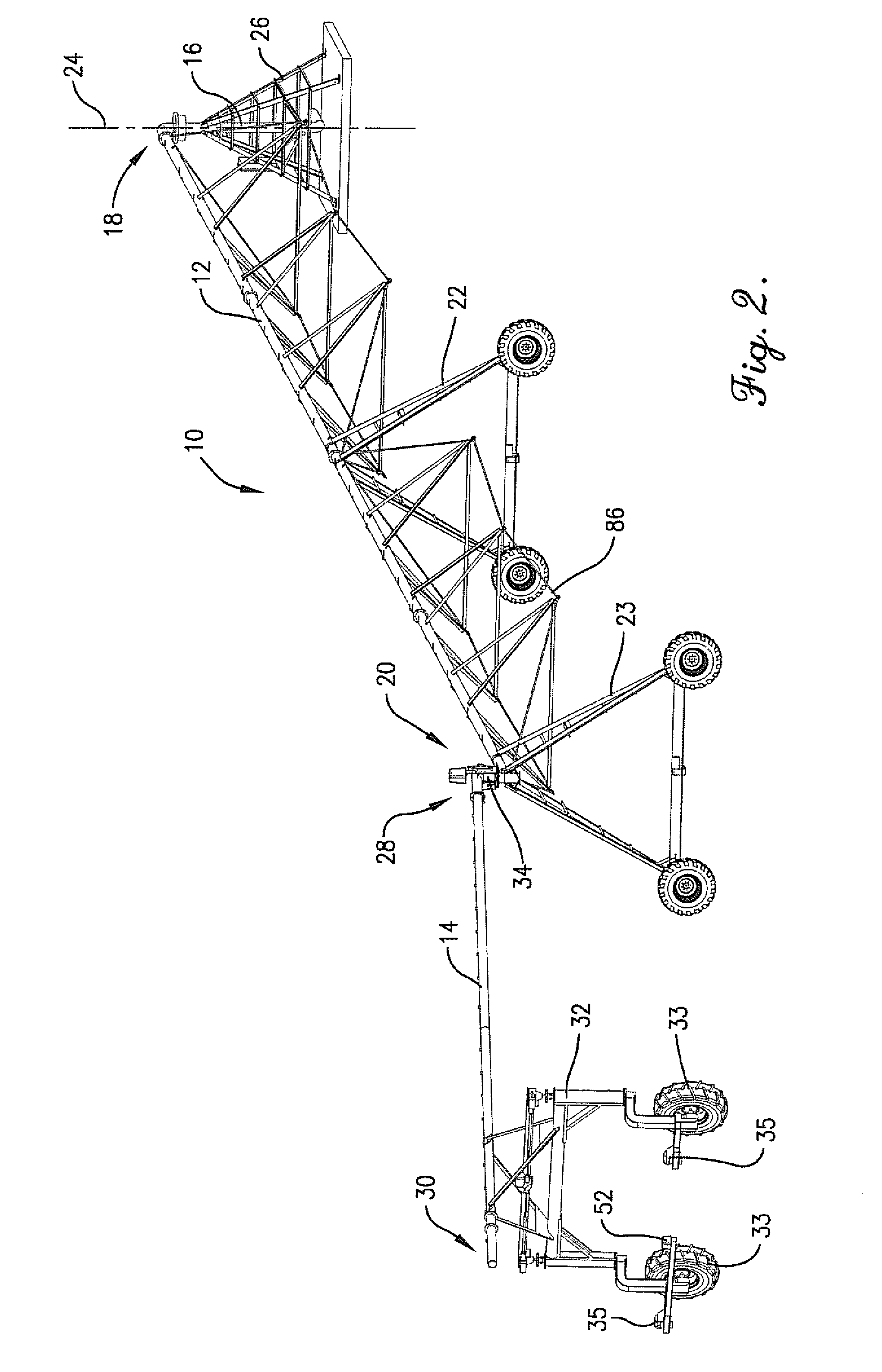
[0018]As illustrated in FIG. 2, a center pivot irrigation machine 10 of embodiments of the present invention comprises a long conduit or main pipeline 12 and a shorter auxiliary pipeline 14, also referred to as a corner unit. Both pipelines 12,14 are configured for carrying irrigation fluid, such as water and / or fertilizer, herbicide, insecticide, or other similar product, which is supplied to the main pipeline 12 via a supply pipeline 16 connected to a water source (not shown).

[0019]The main pipeline 12 includes proximal and distal ends 18,20 and is supported at spaced locations along its length by a plurality of mobile, self-p...


PUM


Abstract

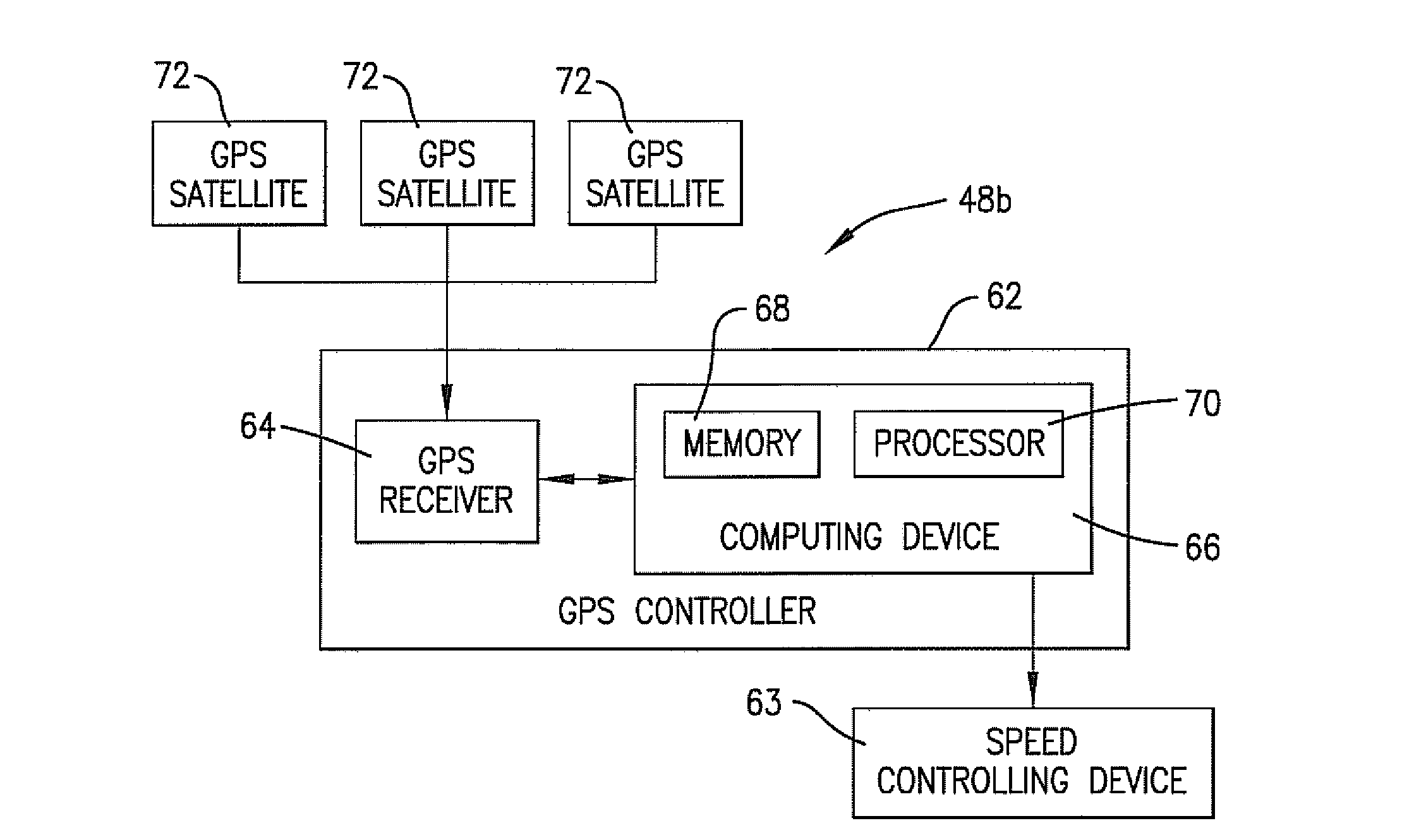
To allow for optimal uniform application of irrigation fluid in a field space outfitted with a center pivot irrigation machine having a main pipeline and an auxiliary or corner pipeline, the auxiliary pipeline is operable to both lead and lag the main pipeline as the main pipeline makes a progressive rotation in a single direction through the field space. In one embodiment a control system for the irrigation machine comprises a buried cable control system. In another embodiment a control system comprises a global positioning satellite control system. In a third embodiment a control system comprises at least two position sensing devices, a first device for sensing an angle of the main pipeline with respect to a center tower and a second device for sensing an angle between the main pipeline and the auxiliary pipeline, and a speed controlling device for controlling a speed of rotation of the main and auxiliary pipelines.

Description

TECHNICAL FIELD[0001]Embodiments of the invention relate to large center pivot irrigation machines of the type utilized in watering crops in a field, and, more particularly, to a method, apparatus, and computer program for controlling an auxiliary pipeline of the irrigation machine to both lead and lag a main pipeline of the machine in a field space.BACKGROUND AND SUMMARY[0002]Center pivot agricultural irrigation machines commonly include a main pipeline supported at intervals on movable towers for rotation about a fixed, center point proximate to an inner, proximal end of the pipeline. Irrigation fluid is supplied to the proximal end of the pipeline and distributed through sprinklers or other fluid emitting devices placed along or supported from the pipeline. The movement of the main pipeline about the center pivot irrigates a circular portion of a field space, herein referred to as a primary field space. In a square-shaped or an irregularly-shaped field space, irrigation of only a...

Claims


Application Information

Patent Timeline
IPC IPC(8): G05B19/43
CPCA01G25/092A01G25/16Y10T137/1866Y02A40/22
Inventor CHOAT, WAYNE D.
Owner LINDSAY CORP
Learn More