WEC with improved power take off apparatus

a technology of power take off and power supply, which is applied in the direction of mechanical equipment, machines/engines, electric generator control, etc., can solve the problems of linear thrust rods, rod needs, and linear thrust rods are among the most expensive and weakest items in current wec designs, so as to improve power capture and ensure the effect of survivability

Active Publication Date: 2010-10-21
OCEAN POWER TECHNOLOGIES
View PDF20 Cites 14 Cited by
  • Summary
  • Abstract
  • Description
  • Claims
  • Application Information

AI Technical Summary

Benefits of technology

[0017]In accordance with one aspect of the invention, a pair of PTO modules located on either side of a spar bearing rail may be interconnected to provide balanced operation.
[0018]In accordance with an aspect of the invention, the spar may be held stationary by either affixing the spar directly to the sea bed or attaching the spar to a structure affixed to the sea bed. This may be done to enhance power capture and the survivability the WEC to stressful weather conditions. A spar formed to have a long stroke power takeoff mechanism enables the float of the WEC to automatically compensate for tidal variation as well as to be positioned for maintenance and storm survival. That is, the spar may be made long enough to allow for tidal variations without having to move the position of the spar. In addition, if the spar is made sufficiently long so it extends (e.g., 10 meters) above the surface of the water it enables a “park” position for maintenance of the WEC and its positioning below the surface of the water (e.g., 15 meters) for storm survival.

Problems solved by technology

A problem with the present technology is that a linear seal system has to be placed at the top of the spar to interface the thrust rod and ensure that water and air will not enter into the spar.
The linear seal is a weak link in the system because it is extremely difficult to provide a reliable seal of this type.
Another problem with current designs is that the thrust rod needs to transfer the relative linear motion between the float and the spar while interfacing with the linear seal.
The linear thrust rod is one of the most expensive and weakest items in current WEC designs.
The thrust rod also has limited scalability in larger systems.

Method used


Image

  • WEC with improved power take off apparatus
  • WEC with improved power take off apparatus
  • WEC with improved power take off apparatus

Examples


Embodiment Construction

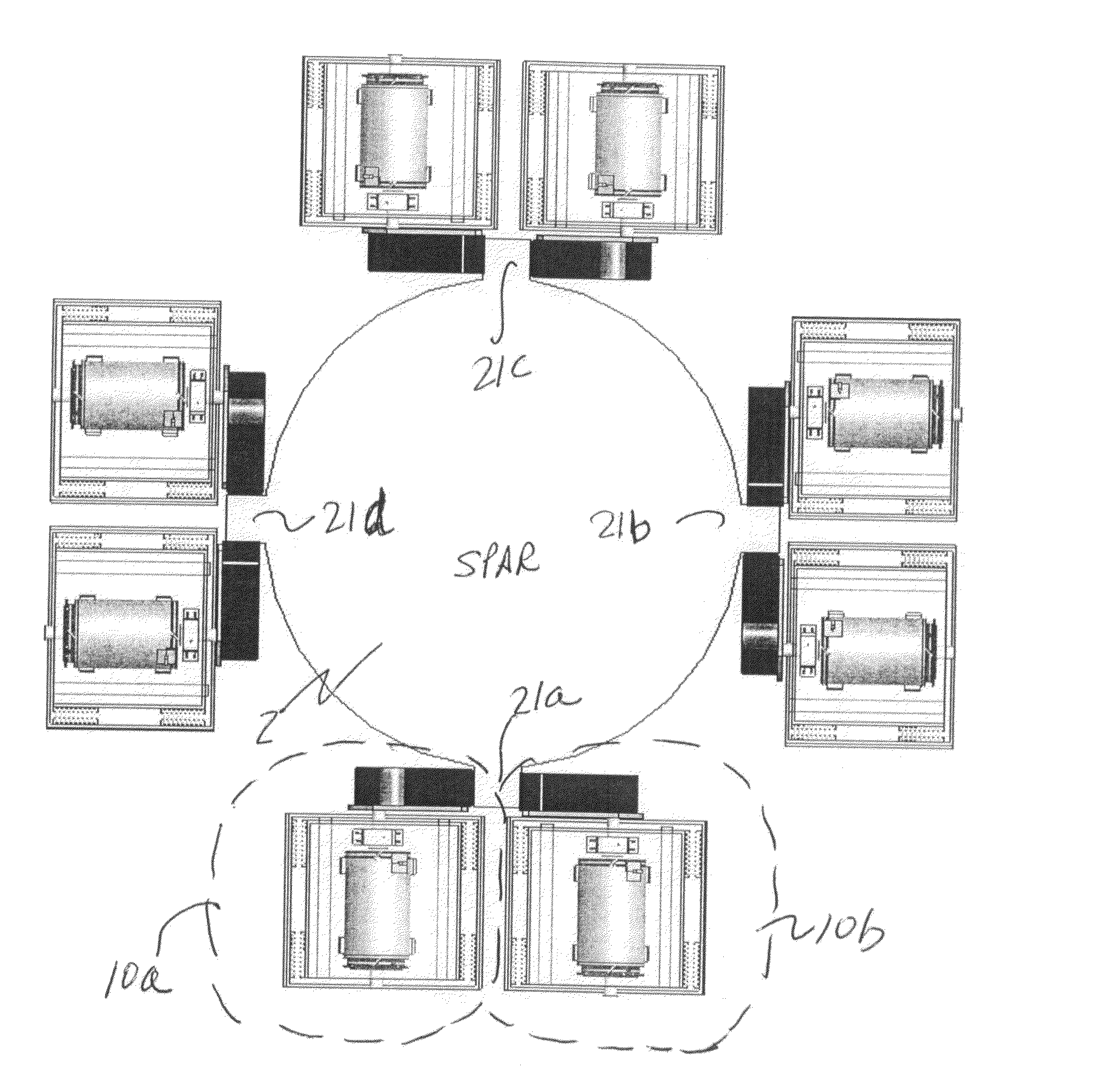
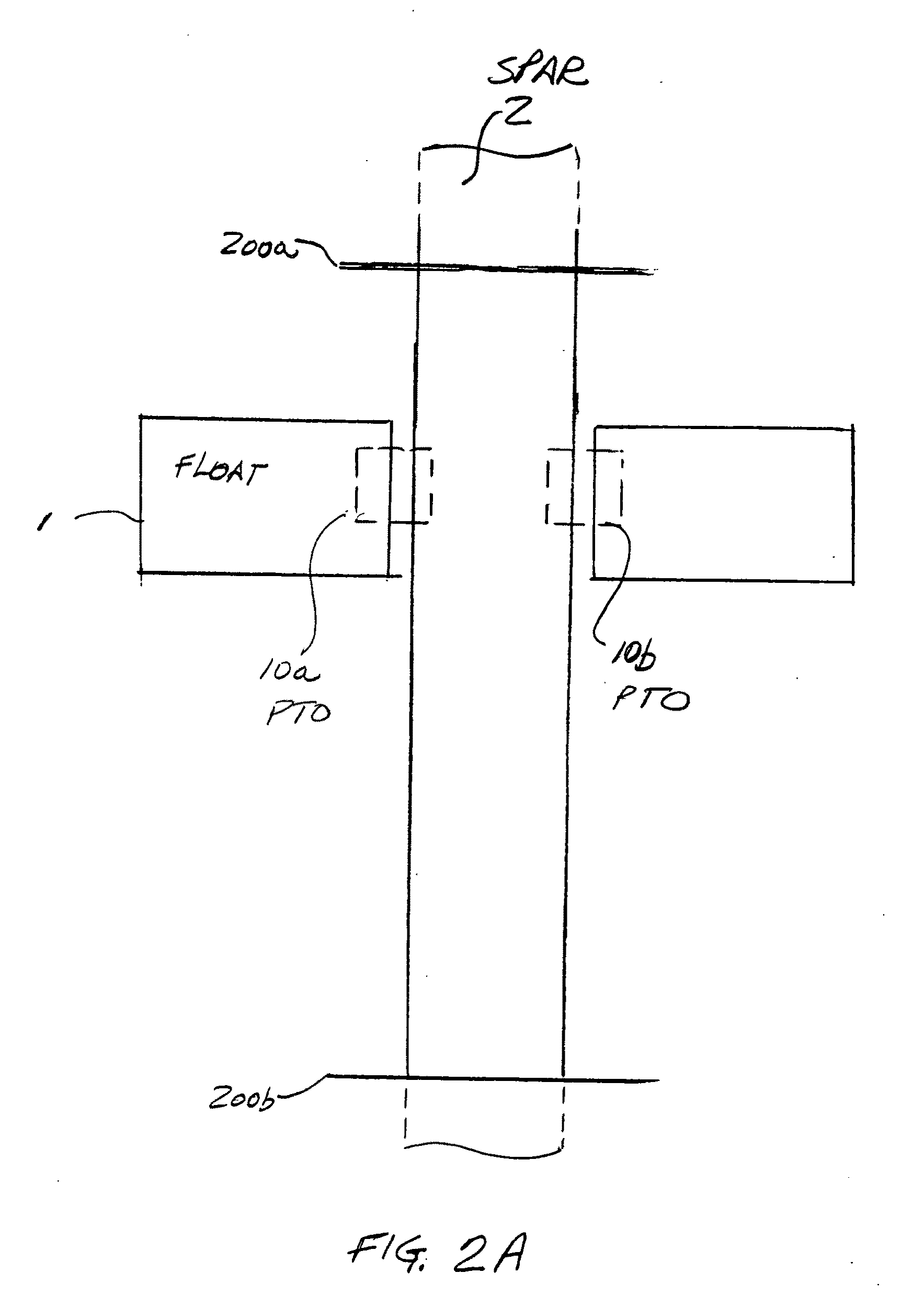
[0034]FIGS. 2A, 2B and 2C illustrate a WEC embodying the invention intended to be subjected to ocean waves. FIGS. 2A and 2C show a float 1 guided along a spar 2 with PTO modules 10a, 10b shown directly connected between the float and the spar. In response to the waves, the float can move along the full length of the spar from an upper stop 200a to a lower stop 200b, as illustrated in FIG. 2C. As noted above, there is no transfer or translation of the movement of the float via a bridge and there is no use of a thrust rod or linear seal, as in the prior art. The power take off (PTO) device of the invention may include a plurality of PTO modules (e.g., 10a, 10b) connected between the spar and float. The dashed boxes identified as 10a and 10b between the float and spar, drawn in FIGS. 2A and 2C, are intended to indicate that the PTO modules of the invention react directly to the conditions existing between the float and the region of the spar proximal to the float.

[0035]The floating ele...


PUM


Abstract

A wave energy converter (WEC) includes a float and a spar for guiding the up and down movement of the float in response to the waves. A power take off (PTO) device coupled between the float and the spar and mounted within one of the float and spar such that the PTO includes apparatus responsive to the mechanical interaction of the float with the portion of the spar in proximity to the float for converting their relative motion into useful energy. In one embodiment the PTO includes a linear rack extending along an external portion of the spar and a linear to rotary converter, mounted within the float, including a double sided toothed belt for engaging the rack and causing rotation of the rotary converter to drive an electric generator. In another embodiment the PTO includes tires mounted within the float which rotate as the float moves up and down. In another embodiment the PTO includes a rack and pinion arrangement with one of them connected to the spar and the other mounted in the float.

Description

[0001]This invention claims priority from provisional application Ser. No. 61 / 211,439 filed Mar. 30, 2009 titled POWER TAKE OFF APPARATUS FOR A WEC, and provisional application Ser. No. 61 / 211,440 filed Mar. 30, 2009 titled POWER TOWER FOR WAVE ENERGY CONVERTER, the teachings of which are fully incorporated herein by reference.BACKGROUND OF THE INVENTION [0002]This invention relates to improved power take off devices (PTO) for use in wave energy conversion systems (WECs).[0003]In general, WECs include: (a) a float (shell) which moves in phase with the waves; (b) a spar or column which is either stationary with respect to the float or moves out of phase relative to the float; and (c) a power take off device (PTO) coupled between the float and spar to convert their relative motion into a useful form of energy (e.g., electric power).[0004]Many different types of PTOs have been suggested. However, there exists a need to have a PTO which is more efficient, more reliable and more economic...

Claims


Application Information

Patent Timeline
Patent Type & Authority Applications(United States)
IPC IPC(8): F03B13/18
CPCF03B13/1855F05B2240/40Y02E10/38F05B2260/504F05B2260/505F05B2260/4031Y02E10/30
Inventor CHI, WEI-MINGHART, PHILIP R.
Owner OCEAN POWER TECHNOLOGIES
Why Eureka
Try Eureka