
Method and System for Estimating and Applying a Step Size Value for LMS Echo Cancellers

a technology of lms echo canceller and step size value, applied in the field of estimating and applying a step size value for lms echo canceller, can solve the problems of reducing the quality of transmission, difficult to obtain in resource-constrained digital signal processing applications, and high computation intensity of their implementation, so as to improve the accuracy of coefficient update and significant processing efficiency

Active Publication Date: 2010-10-14
INTELLECTUAL VENTURES II
View PDF7 Cites 0 Cited by
  • Summary
  • Abstract
  • Description
  • Claims
  • Application Information

AI Technical Summary

Benefits of technology

This approach results in significant processing efficiency and improved precision, enabling deep convergence and enhanced echo cancellation performance with reduced processor usage, particularly effective for applications with wide dynamic range signals like speech.

Problems solved by technology

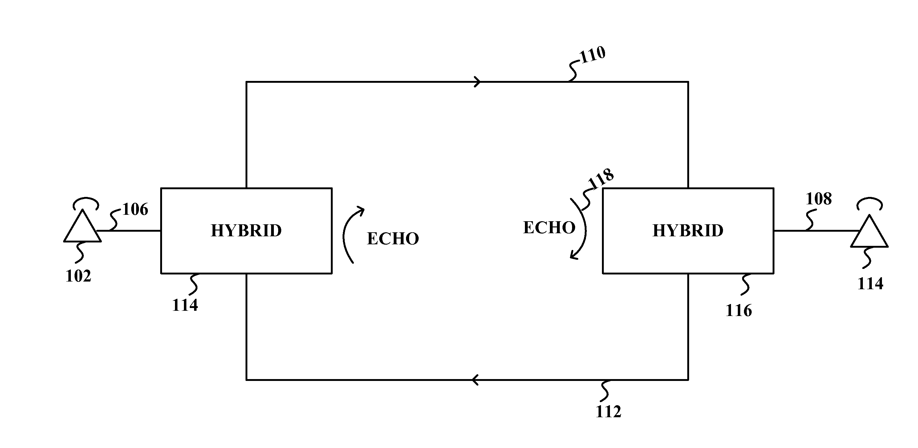
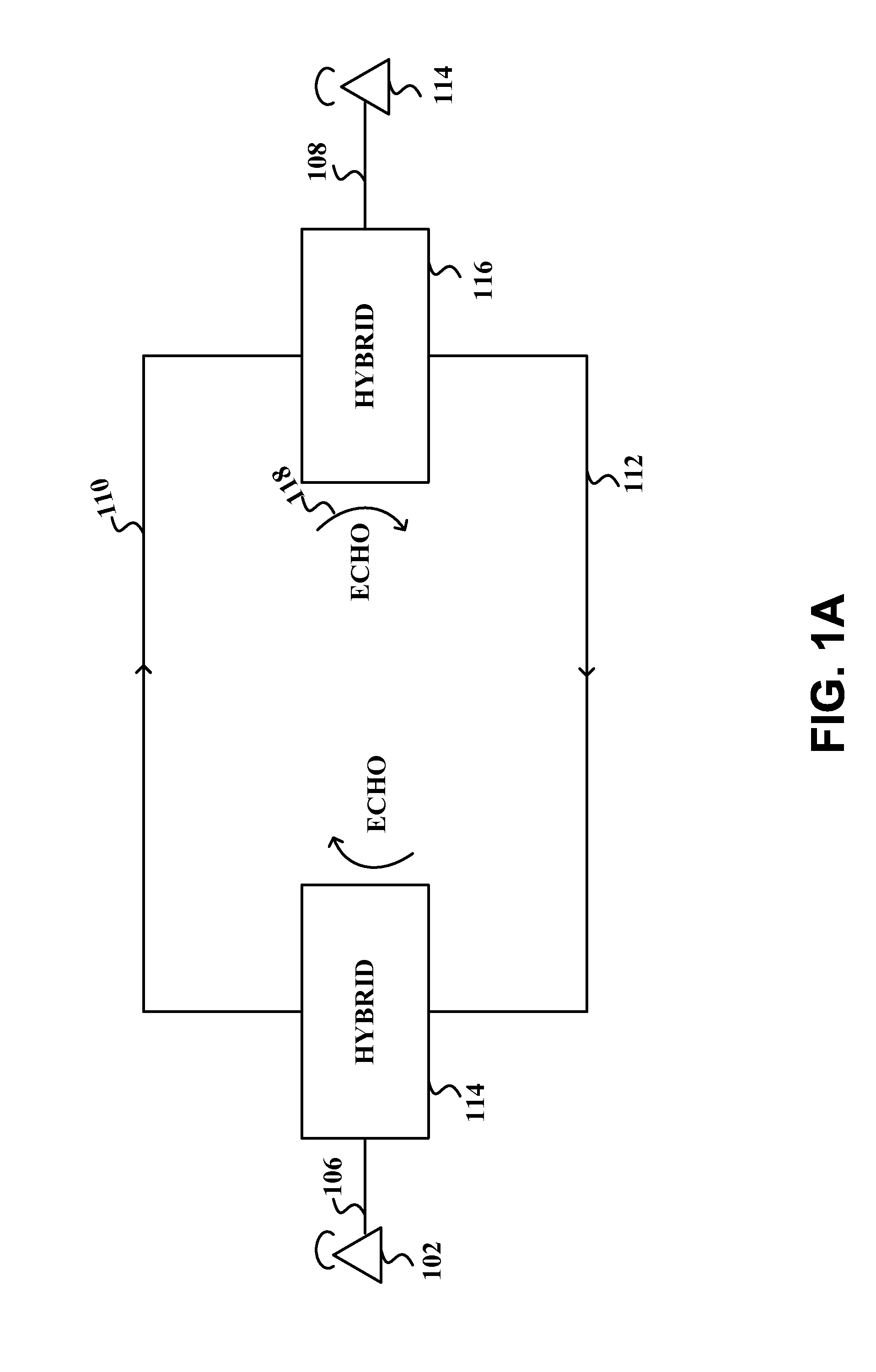
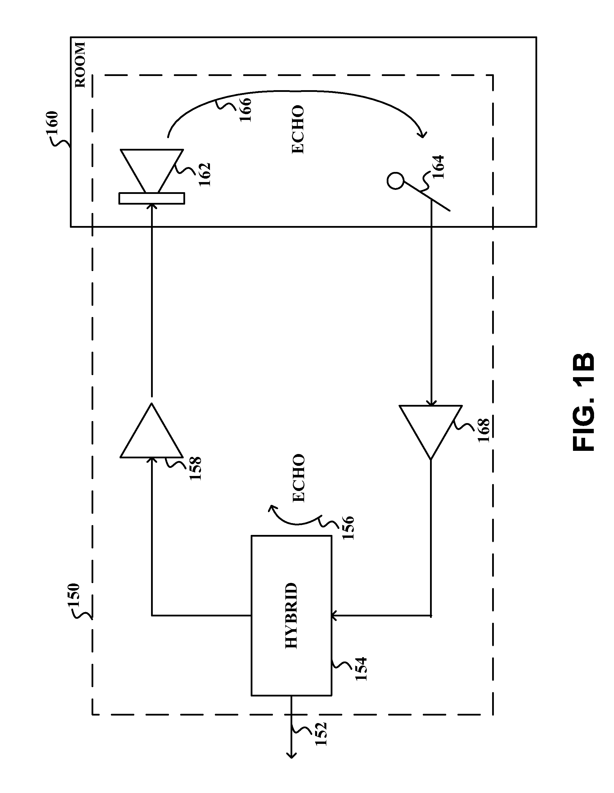
Echo is a well known impairment of telecommunication systems which causes a degradation in the quality of transmission.
One current problem with these algorithms is that their implementation is highly computation intensive, and optimal performance, i.e., deep convergence, is difficult to obtain in resource constrained digital signal processing applications.
In particular, it is the adaptation algorithms (i.e., coefficient calculation) that require a significant amount of processing power.
The impact of value truncation is a loss of precision especially for small update values and this has the effect of preventing the echo canceller from reaching its optimal performance.
Furthermore, division is a mathematical operation that is not supported by almost all digital signal processors because it is hardware intensive to implement.
The inverse function is an iterative algorithm that is itself computationally intensive.
As such, prior art implementations of LMS echo cancellers tend to be computationally intensive and incur precision errors that degrade echo canceller performance.

Method used


Image

  • Method and System for Estimating and Applying a Step Size Value for LMS Echo Cancellers
  • Method and System for Estimating and Applying a Step Size Value for LMS Echo Cancellers
  • Method and System for Estimating and Applying a Step Size Value for LMS Echo Cancellers

Examples


Embodiment Construction

[0019]FIG. 2 shows a high level block diagram of a network architecture which includes an echo canceller 214. As shown in FIG. 2, X(n) is the signal received on line 202 from the far end telephone (not shown), also called the excitation signal. As discussed above, in a typical network architecture, line 202 may be a four-line trunk which carries voice signals from the far end telephone to the near end telephone 204. The hybrid 206 directs the signal energy arriving from the far end telephone via trunk line 202 to the two wire subscriber loop 208 without allowing it to return to the far end telephone via trunk line 210. However, as discussed above, some portion of the excitation signal X(n) gets reflected back on line 210 as an echo due to an impedance mismatch, and this echo gets added to the signal U(n) which originates at near end telephone 204. The resulting signal is Y(n). The near end telephone signal U(n) will be zero or near-zero considering ambient noise when only the user o...


PUM


Abstract

Disclosed is an improved method and apparatus for estimating and applying a step size value for a least mean squares echo canceller. A power estimate of an excitation signal is compared to a reference power level to determine a shift adjustment. The shift adjustment is added to a reference shift amount to determine a shift amount. The product of an excitation signal and an error signal is then calculated and the product is stored in a memory register comprising a plurality of bits. The bits stored in the memory register are shifted either left or right based upon the shift amount. The shift adjustment may be based in part upon the ratio of the excitation signal power estimate and the reference power level.

Description

CROSS-REFERENCE TO RELATED APPLICATIONS[0001]This application is a continuation of U.S. patent application Ser. No. 10 / 978,204 entitled “Method and System for Estimating and Applying a Step Size Value for LMS Echo Cancellers,” filed Oct. 29, 2004, now pending, which is fully incorporated herein by reference for all purposes.BACKGROUND OF THE INVENTION[0002]The present invention relates generally to echo cancellers, and more particularly to estimating and applying a step size value for least mean squares echo cancellers.[0003]Echo is a well known impairment of telecommunication systems which causes a degradation in the quality of transmission. One type of echo is a result of the design of a typical telephony network and is illustrated in FIG. 1A which shows a simplified connection between two telephones 102 and 104. Subscriber 102 is connected to the network via two-wire subscriber loop 106 and subscriber 104 is connected to the network via two-wire subscriber loop 108. The two-wire ...

Claims


Application Information

Patent Timeline
Patent Type & Authority Applications(United States)
IPC IPC(8): G06F17/10
CPCH04B3/23
Inventor PIETROWICZ, STANLEY
Owner INTELLECTUAL VENTURES II
Learn More