
Relay Communication Method of Next Generation Cellular Communication System

Active Publication Date: 2010-10-14
KAIFI LLC
View PDF5 Cites 11 Cited by
  • Summary
  • Abstract
  • Description
  • Claims
  • Application Information

AI Technical Summary

Benefits of technology

[0010]Accordingly, the present invention has been made keeping in mind the above problems occurring in the prior art, and an object of the present invention is to provide a method of performing relay communication in a next generation cellular communication system, which expands the wave

Problems solved by technology

Therefore, in the case in which an omnidirectional antenna is used, communication is not possible if a terminal locates out of a region of several tens of meter in which a LOS channel is ensured.
Therefore, the system has a restriction in that it can only be used for short-range communication.
However, in the case in which this is expanded to a general communication system, such as a cellular communication system, a high gain can be realized using an antenna array, but it is considerably difficult to support a user for whom a LOS channel is not ensured.
That is, although the use of a repeater can be considered as an example of supporting a user for whom a LOS channel is not ensured, this may impose a burden on the entire communication system.

Method used


Image

  • Relay Communication Method of Next Generation Cellular Communication System
  • Relay Communication Method of Next Generation Cellular Communication System
  • Relay Communication Method of Next Generation Cellular Communication System

Examples


Embodiment Construction

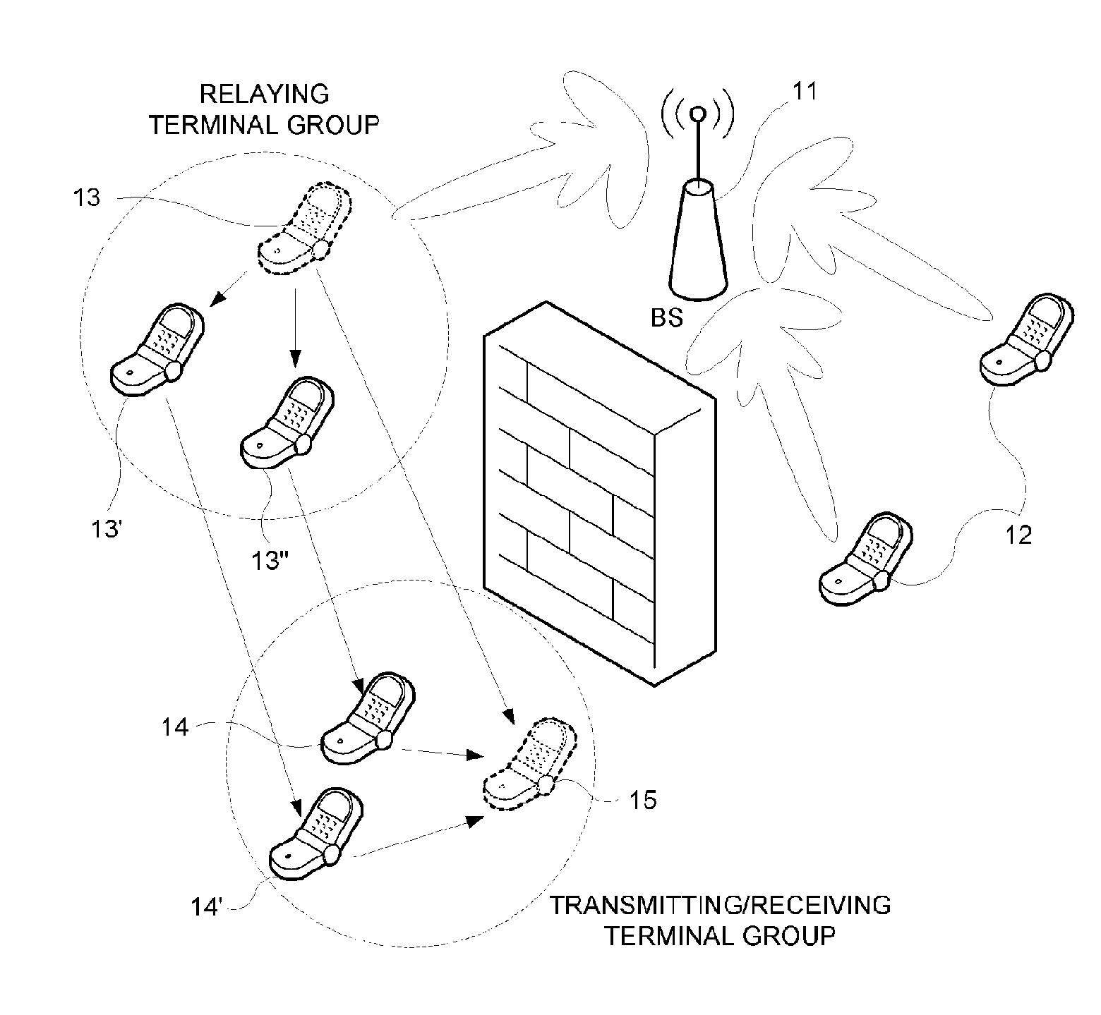
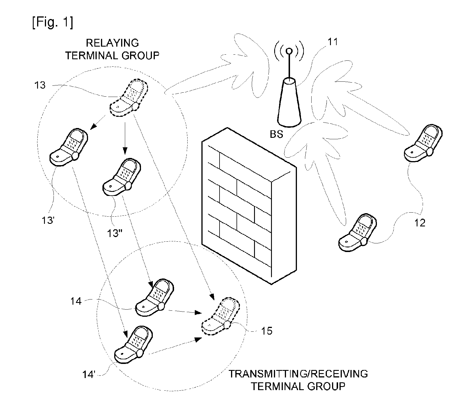
[0016]It is assumed that the next generation cellular communication system, to which the present invention is applied, uses a high frequency band of several tens of GHz. Although the next generation cellular communication system can use a 2 GHz or lower band, similar to that used at present, this may be ineffective in view of propagation characteristics, the size of the antenna, and the antenna separation distance which are formed by a wavelength of carrier wave. The present invention enables a signal to be transmitted or received to or from a terminal, which acquires a LOS channel, by utilizing a beamforming method using the antenna array of a base station. Here, the terminal may have one or more antennas.

[0017]In the present invention, a LOS channel terminal is a terminal which acquires a LOS channel with a base station, and a non-LOS channel terminal is a terminal which does not acquired a LOS channel with a base station. Further, a LOS channel terminal group is a group of the LO...


PUM


Abstract

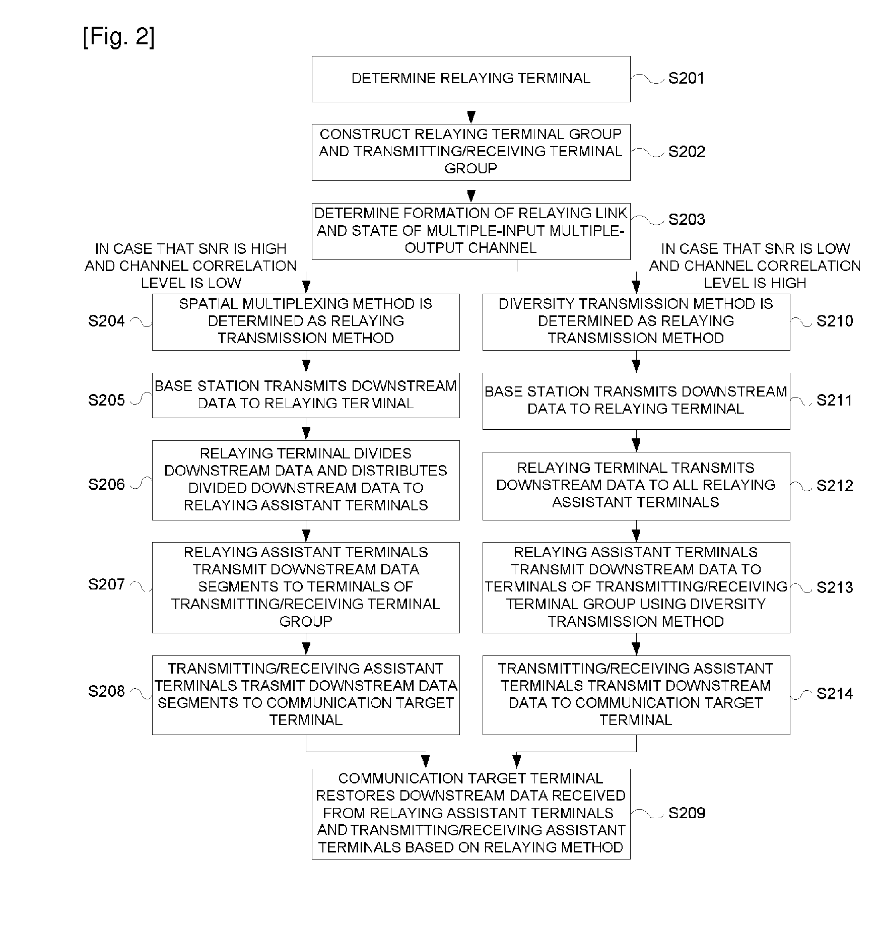
A method of performing relay communication in a next generation cellular communication system is disclosed. The next generation cellular communication system includes a base station and a plurality of terminals, and a communication target terminal which has not acquired a Line-Of-Sight (LOS) channel with the base station performs communication through the relay of a relaying terminal which has acquired a LOS channel. The base station determines the relaying terminal. The relaying terminal forms a relaying terminal group by determining one or more relaying assistant terminals. The communication target terminal forms a transmitting/receiving terminal group by determining one or more transmitting/receiving assistant terminals. The base station performs communication with the relaying terminal through the relaying terminal, relaying assistant terminals of the relaying terminal group and the transmitting/receiving assistant terminals of the transmitting/receiving terminal group.

Description

BACKGROUND OF THE INVENTION[0001]1. Field of the Invention[0002]The present invention relates to a method of performing relay communication by constructing a relaying terminal group and a transmitting / receiving terminal group and then using cooperation between the groups, so as to realize effective communication between a base station and one or more terminals in a next generation cellular communication system which uses a band of several tens of GHz.[0003]2. Description of Related Art[0004]Currently, a cellular communication system provides voice or data service to users in a relatively wide area using a 2 GHz or lower frequency band. In the case of current service, since a low speed service, the maximum speed of which is several Mbps, is provided, the narrow bandwidth does not matter. Further, since the 2 GHz or lower frequency band has relatively good propagation characteristics, communication can be sufficiently realized, even though a Line-Of-Sight (LOS) channel is not ensured....

Claims


Application Information

Patent Timeline
IPC IPC(8): H04W40/00
CPCH04B7/2606H04W88/04H04W4/06H04W40/02H04W84/04
Inventor CHO, DONG HOYU, HEE JUNGOH, YOUNG SEOKLEE, HO WONLEE, WOONG SUPLEE, YONG HOON
Owner KAIFI LLC
Learn More