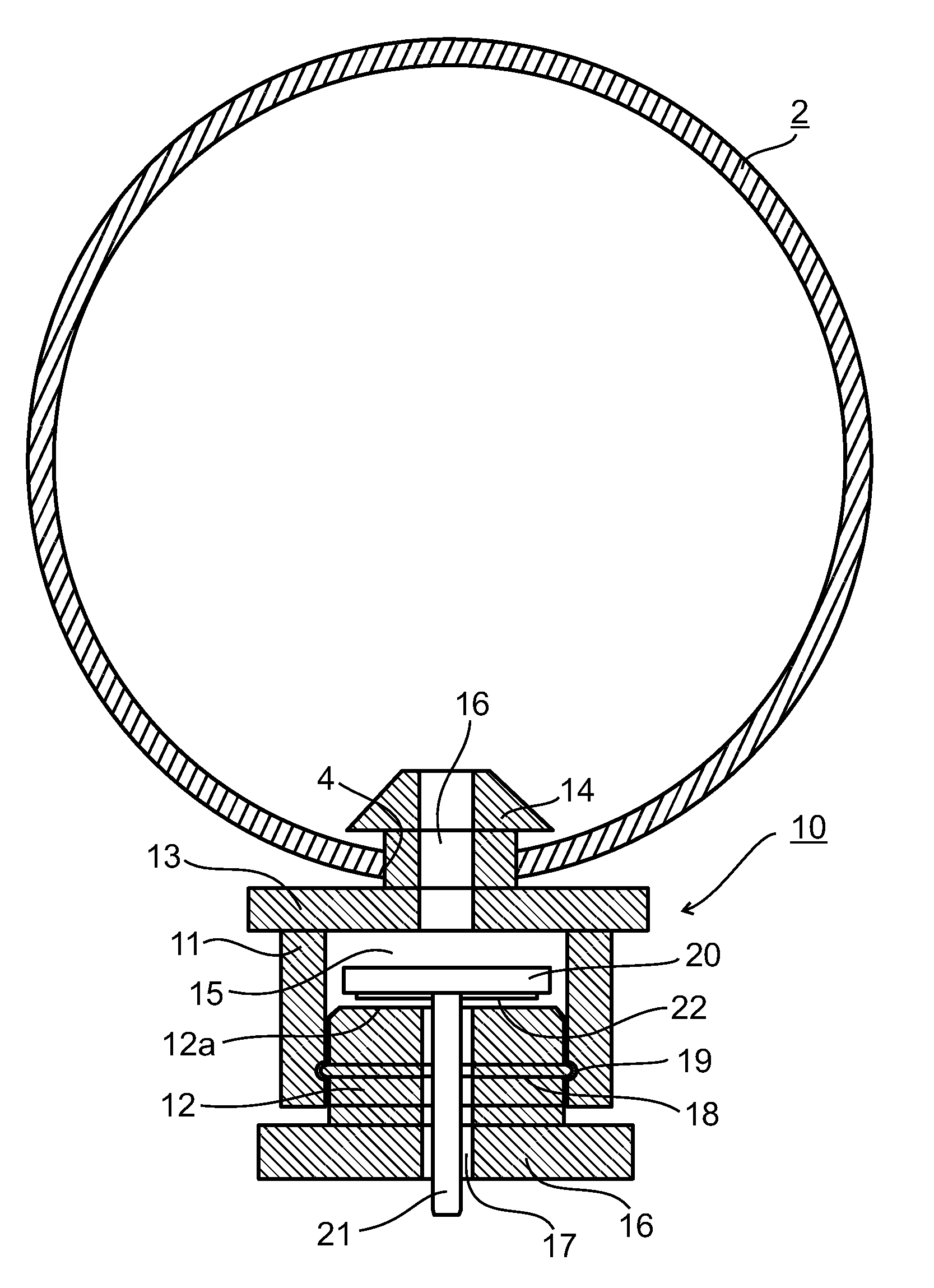
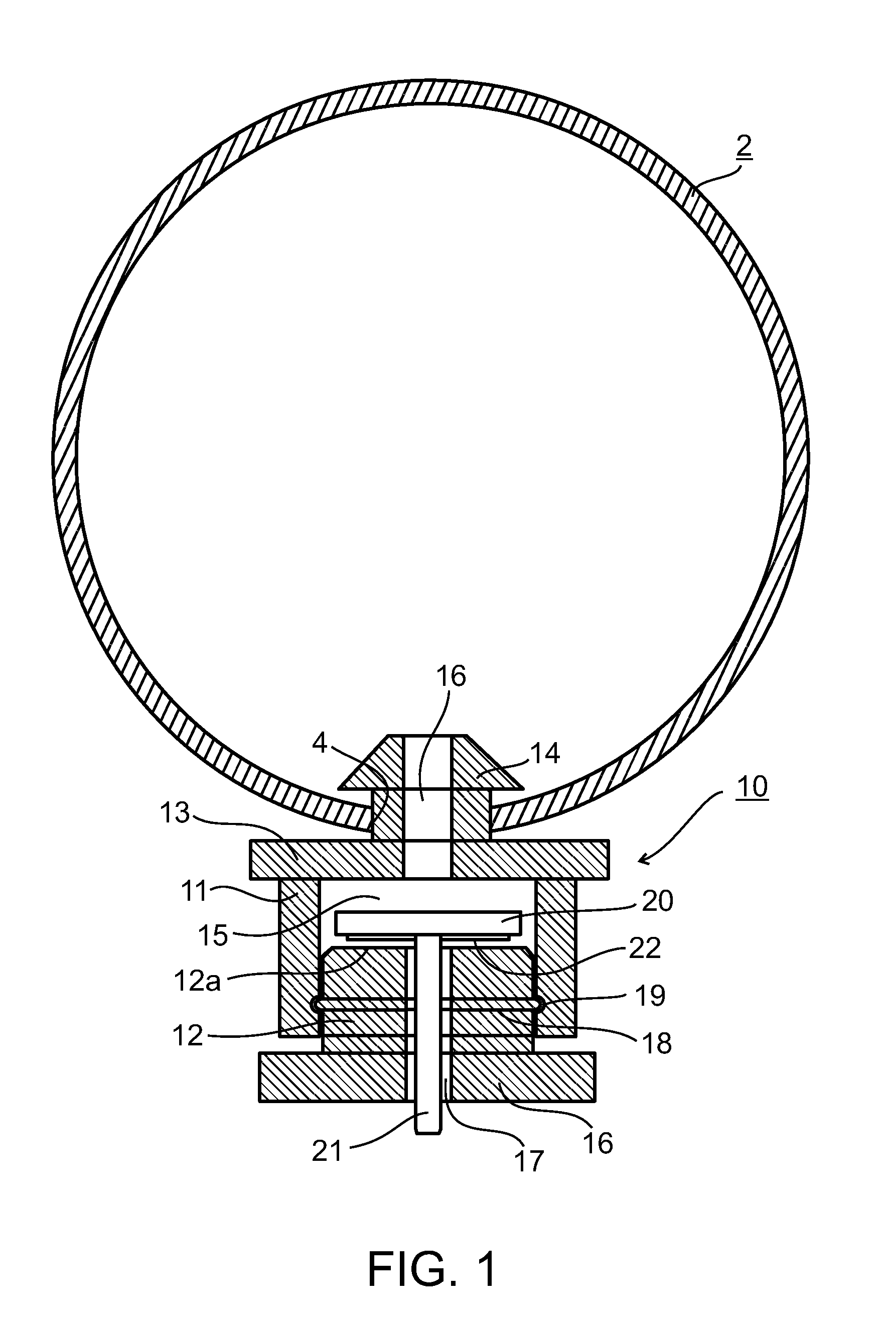
Fluid control devices particularly useful in drip irrigation emitters
a technology of flow control and drip irrigation, which is applied in the direction of mechanical equipment, lighting and heating equipment, combustion types, etc., can solve the problems of insufficient pressure drop, simple orifice emitters are often blocked, and the flow rate of drip irrigation is generally not capable of less than 1.2 l per hour, etc., to achieve simple and inexpensive manufacturing, easy to use and clean
- Summary
- Abstract
- Description
- Claims
- Application Information
AI Technical Summary
Benefits of technology
Problems solved by technology
Method used
Image

Examples
example 1
[0055]For a round orifice of diameter 1.0 mm the cross sectional area is 0.00785 cm2. Under a pressure of 2.0 bars the flow rate is obtained: Q=15.7 cm3 / s=56.5 L / h.
example 2
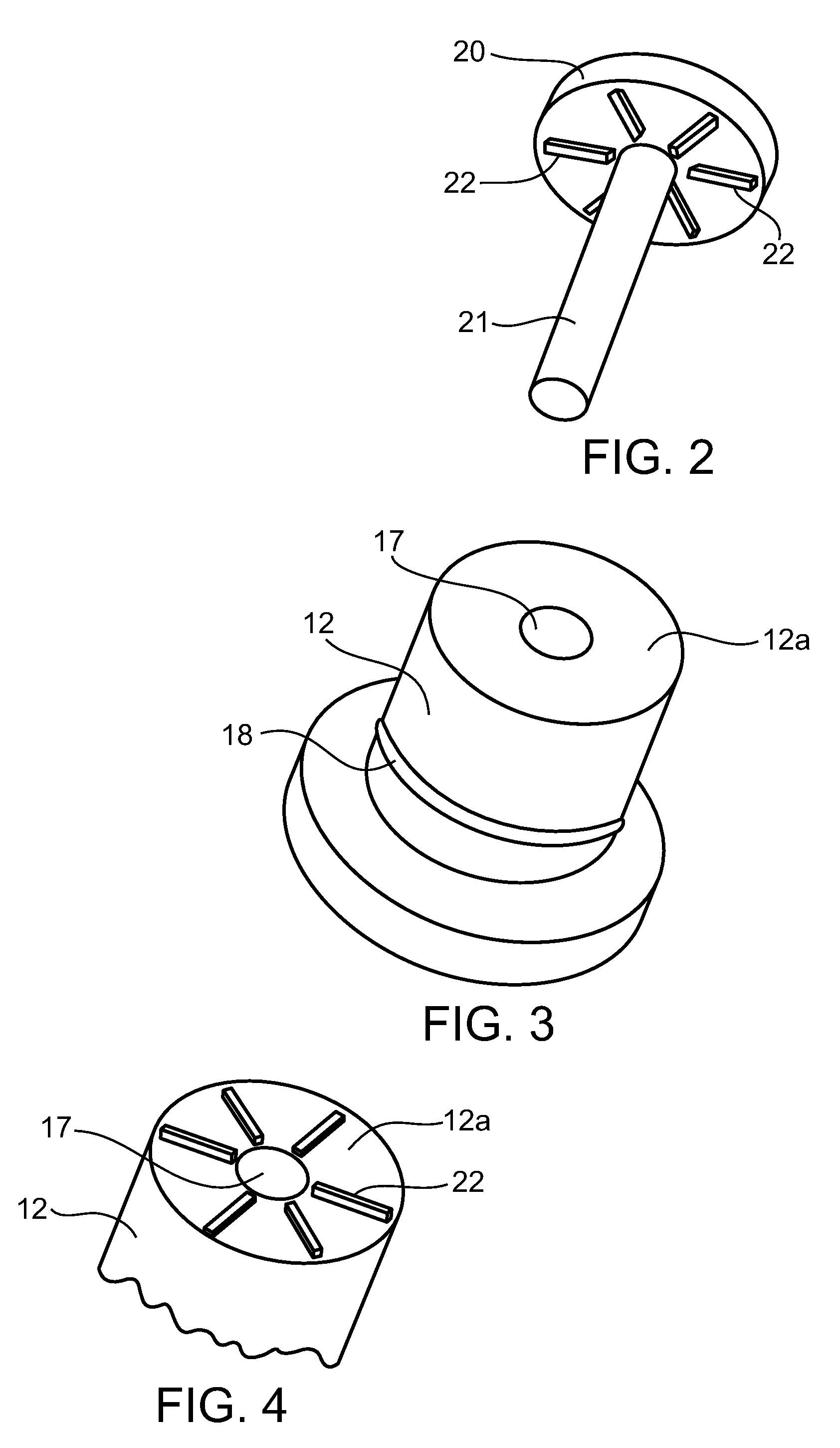
[0056]For the same size round orifice of diameter D=1.0 mm, covered by a slab having 6 radial ribs each protruding h=0.005 mm and width w=0.4 mm of its face, the gateway cross sectional area is: (πD-4w)h=3.7×10⁻⁵ cm2. Under a pressure of 2 bars the flow rate is obtained: Q=3.7×10−5·(1.4·103·1.4)=0.074 cm3 / s=0.27 L / h. This flow rate is in compliance with the discharge known as “Micro-Drip”.
[0057]While the invention has been described with respect to several preferred embodiments, it will be appreciated that these are set forth merely for purposes of example. Thus, the illustrated flow control device could be used for controlling the flow of other fluids, particularly where very low discharge rates are desirable. In addition, other surface configurations could be used, between the control disc and / or base member to define the passageways for the outflow of the fluid. Many other modifications, variations and applications of the invention will be apparent.
PUM
 Abstract
Description
Claims
Application Information
 - R&D
- Intellectual Property
- Life Sciences
- Materials
- Tech Scout
- Unparalleled Data Quality
- Higher Quality Content
- 60% Fewer Hallucinations
Browse by: Latest US Patents, China's latest patents, Technical Efficacy Thesaurus, Application Domain, Technology Topic, Popular Technical Reports.
© 2025 PatSnap. All rights reserved.Legal|Privacy policy|Modern Slavery Act Transparency Statement|Sitemap|About US| Contact US: help@patsnap.com