Shielded cable
a shielding cable and shielding technology, applied in the direction of insulated conductors, power cables, cables, etc., can solve the problems of affecting the gain of the antenna, the resonance frequency varies by the length of the connected set ground gnd, and the antenna portion has a very complicated structure, etc., to achieve excellent design properties and low cost
- Summary
- Abstract
- Description
- Claims
- Application Information
AI Technical Summary
Benefits of technology
Problems solved by technology
Method used
Image
Examples
first embodiment
1. First Embodiment
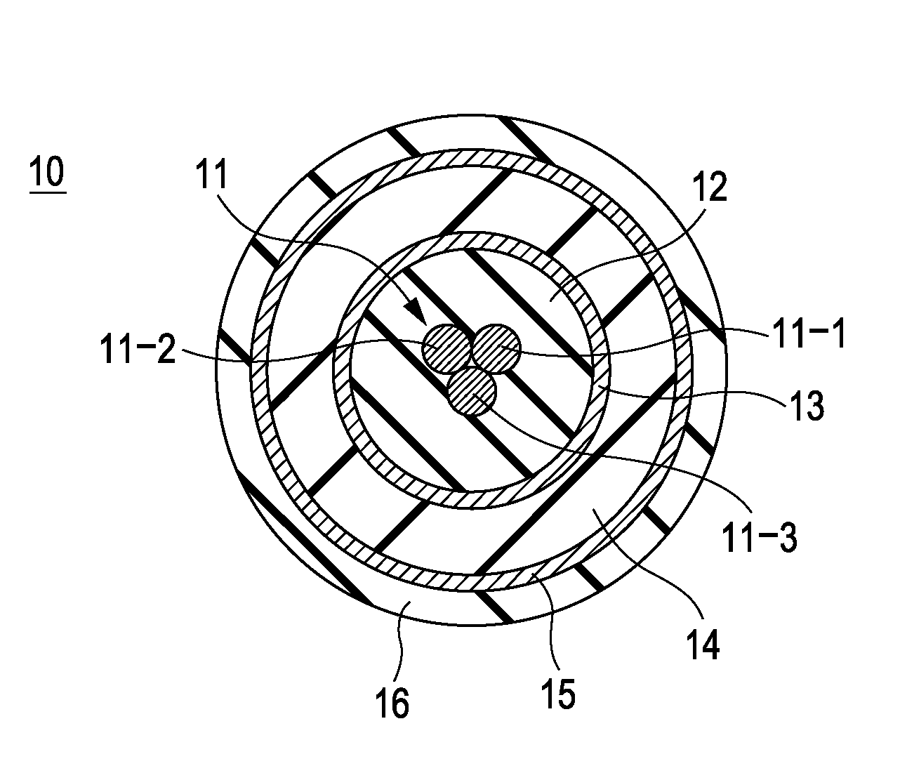
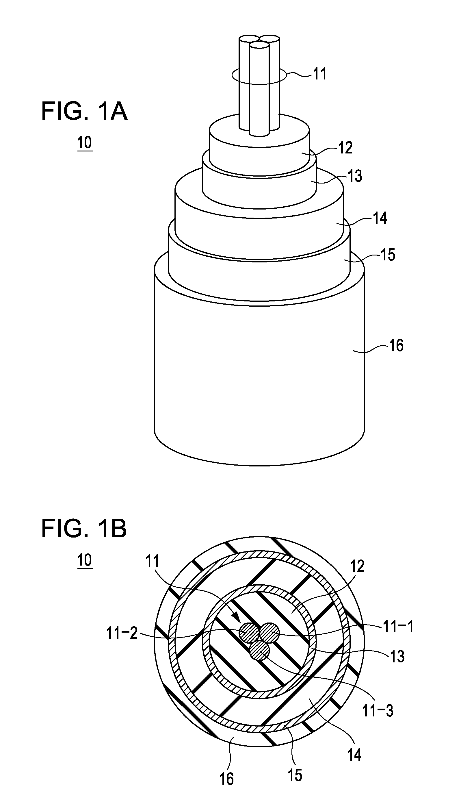
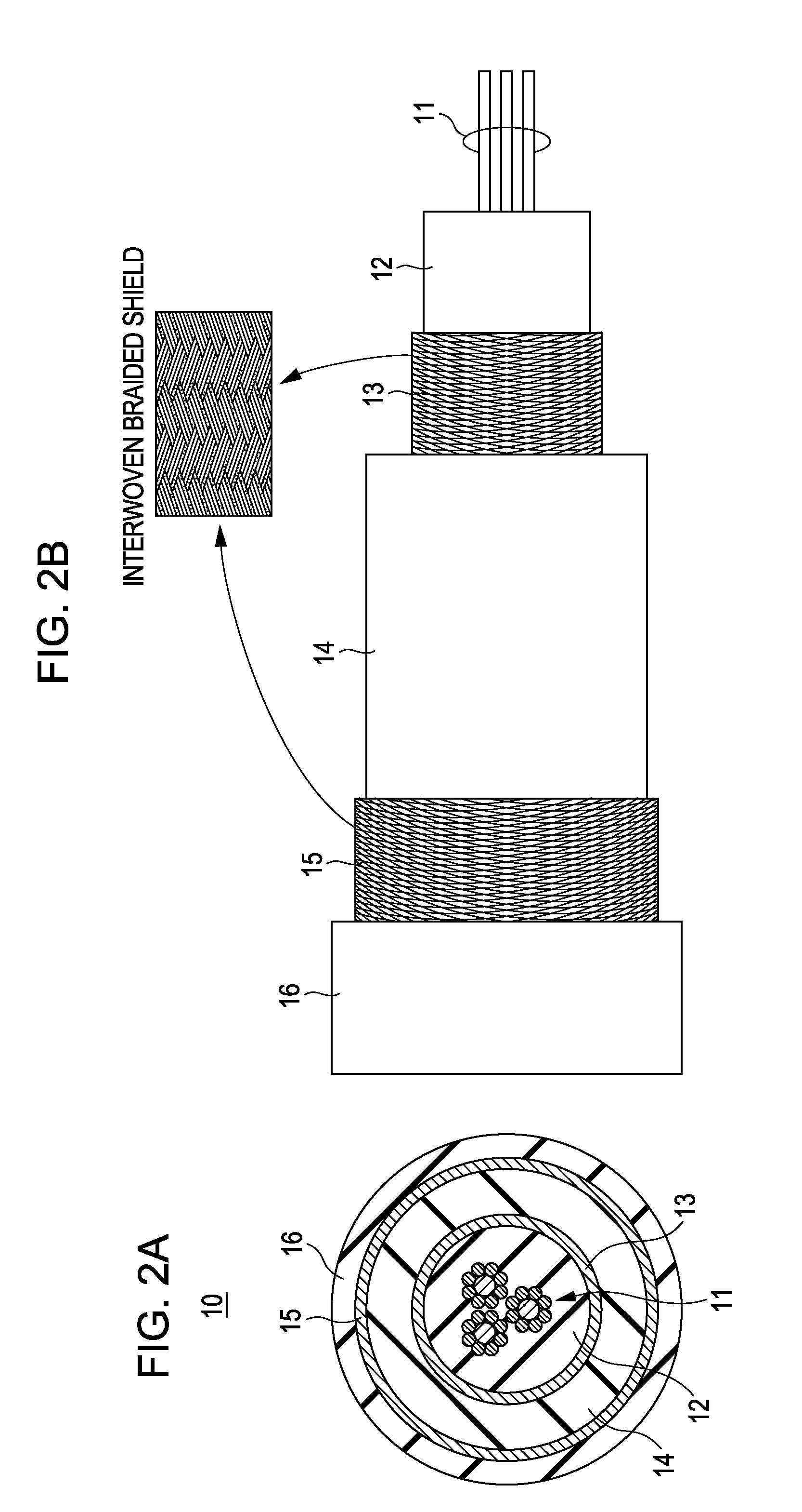
[0078]FIGS. 1A, 1B, 2A, and 2B are diagrams showing a structure example of a shielded cable according to the first embodiment of the present invention.
[0079]FIG. 1A is a perspective view showing each constituent member of the shielded cable according to the first embodiment in an exposed state. FIG. 1B is a simple cross-sectional view of the shielded cable according to the first embodiment.
[0080]FIG. 2A is a simple cross-sectional view of the shielded cable according to the first embodiment, and FIG. 2B is a side view showing each constituent member of the shielded cable according to the first embodiment in an exposed state.
[0081]A shielded cable 10 of this embodiment is formed as a coaxial and double shielded cable. In other words, the shielded cable 10 of this embodiment has a double coaxial cable structure.
[0082][Configuration of Double Shielded Cable]
[0083]The shielded cable 10 includes an inner conductor (there is also a case where it is called a central cond...
second embodiment
2. Second Embodiment
[0165]FIGS. 10A, 10B, 11A, and 11B are diagrams showing a structure example of a shielded cable according to a second embodiment of the present invention.
[0166]FIG. 10A is a perspective view showing each constituent member of the shielded cable according to the second embodiment in an exposed state. FIG. 10B is a simple cross-sectional view of the shielded cable according to the second embodiment.
[0167]FIG. 11A is a simple cross-sectional view of the shielded cable according to the second embodiment. FIG. 11B is a side view showing each constituent member of the shielded cable according to the second embodiment in an exposed state.
[0168]Differences between the shielded cable 10A according to the second embodiment and the shielded cable 10 according to the first embodiment are as follows.
[0169]That is, the shielded cable 10A according to the second embodiment is configured such that a coupling state of the second insulator 14 and the first outer conductor 13 is eq...
third embodiment
3. Third Embodiment
[0194]FIGS. 13A to 13C are diagrams showing a configuration example of the antenna device according to the third embodiment of the present invention.
[0195]FIG. 13A is a diagram showing a constructive concept of the antenna device according to the third embodiment.
[0196]FIG. 13B is a diagram showing an equivalent circuit of the antenna device according to the third embodiment.
[0197]FIG. 13C is a diagram showing a specific configuration example of the antenna device according to the third embodiment.
[0198]In the antenna device 30, basically, the shielded cables 10 and 10A according to the first and second embodiments are applied as a shielded antenna cable 10B of the antenna.
[0199]Therefore, in the shielded antenna cable 10B shown in FIGS. 13A to 13C, the same constituent portions as those of the shielded cables 10 and 10A are denoted by the same reference numbers.
[0200]In the antenna device 30, the shielded antenna cable 10B has a first connection portion 40 on one...
PUM
| Property | Measurement | Unit |
|---|---|---|
| dielectric constant | aaaaa | aaaaa |
| dielectric constant | aaaaa | aaaaa |
| outer diameter | aaaaa | aaaaa |
Abstract
Description
Claims
Application Information
 - R&D
- Intellectual Property
- Life Sciences
- Materials
- Tech Scout
- Unparalleled Data Quality
- Higher Quality Content
- 60% Fewer Hallucinations
Browse by: Latest US Patents, China's latest patents, Technical Efficacy Thesaurus, Application Domain, Technology Topic, Popular Technical Reports.
© 2025 PatSnap. All rights reserved.Legal|Privacy policy|Modern Slavery Act Transparency Statement|Sitemap|About US| Contact US: help@patsnap.com


