Snowblower Attachment

a technology for snowblowers and attachments, which is applied in the direction of cleaning ways, constructions, and ways, etc., and can solve problems such as endangering the machine, its operator and nearby persons and objects

Inactive Publication Date: 2010-09-23
MUSCARELLA JOSEPH
View PDF28 Cites 9 Cited by
  • Summary
  • Abstract
  • Description
  • Claims
  • Application Information

AI Technical Summary

Problems solved by technology

Existing snowblowers have various deficiencies when operated on unpaved surfaces such as gravel driveways.
In particular, pieces of gravel can get propelled through and discharged by the snowblower, thereby endangering the machine, its operator and nearby persons and objects.

Method used


Image

  • Snowblower Attachment
  • Snowblower Attachment
  • Snowblower Attachment

Examples


Embodiment Construction

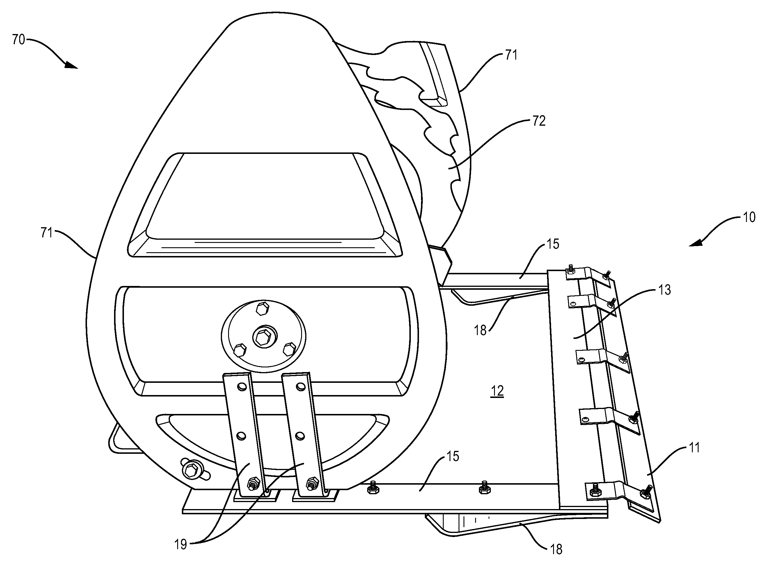
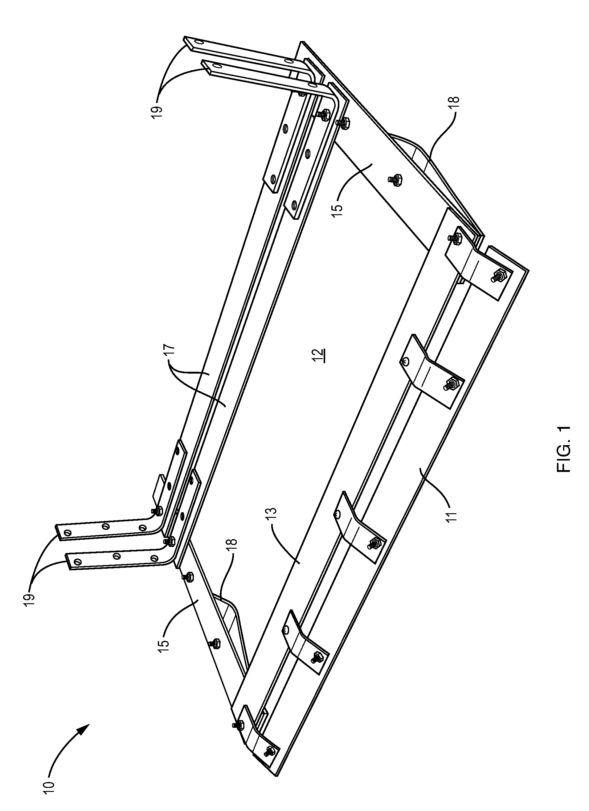
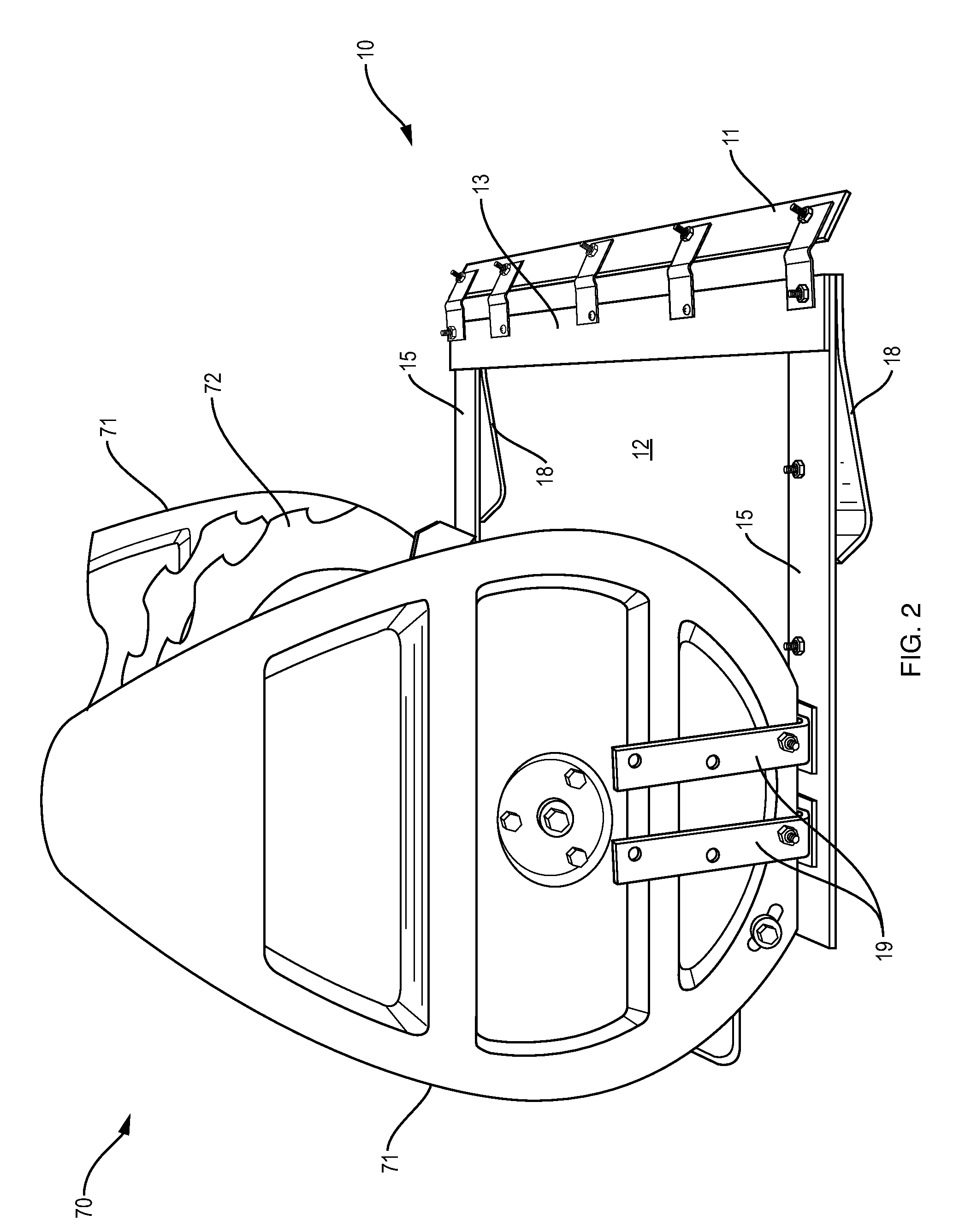
[0011]FIG. 1 is a perspective view of an embodiment of a snowblower attachment in accordance with principles of the present invention. A snowblower attachment 10 comprises one or more front struts 13, one or more rear struts 17, two or more side rails 15, two or more skids 18, and a substantially planar protective guard plate 12. In addition, a snowblower attachment 10 may further comprise a bumper 11 and two or more brackets 19 for attachment to a snowblower.

[0012]In the embodiment of a snowblower attachment 10 as depicted in FIG. 1, a front strut 13 and two rear struts 17 are substantially parallel to the front edge of the guard plate 12 and to each other and attached to two side rails 15 that are oriented perpendicularly to the front edge of the guard plate 12 and to the front and rear struts. A protective guard plate 12 is positioned on top of the front strut 13, rear struts 17 and side rails 15. Skids 18 are attached to the bottom surface of the side rails 15 towards the front ...


PUM


Abstract

A snowblower attachment includes a protective guard plate and attached skids for keeping an impeller of a snowblower from contacting the ground below the snowblower.

Description

CROSS-REFERENCE TO RELATED APPLICATIONS[0001]This application claims priority to U.S. Provisional Application No. 61 / 162,313 filed Mar. 22, 2009, the entire contents of which are hereby incorporated by reference, as if fully set forth herein.FIELD OF THE INVENTION[0002]The present invention relates generally to the field of motorized snowblowers, and more particularly to an attachment device that is used to facilitate use of a snowblower on an unpaved surface.BACKGROUND OF THE INVENTION[0003]Existing snowblowers have various deficiencies when operated on unpaved surfaces such as gravel driveways. In particular, pieces of gravel can get propelled through and discharged by the snowblower, thereby endangering the machine, its operator and nearby persons and objects.[0004]Therefore a need exists for a snowblower or attachment for a snowblower that permits the use of a snowblower on an unpaved surface such as a gravel driveway without throwing gravel.[0005]A device constructed according ...

Claims


Application Information

Patent Timeline
Patent Type & Authority Applications(United States)
IPC IPC(8): E01H5/09
CPCE01H5/098
Inventor MUSCARELLA, JOSEPH
Owner MUSCARELLA JOSEPH
Why Eureka
Try Eureka