
Device, method and computer program product

Inactive Publication Date: 2010-09-16
SONY CORP +1
View PDF28 Cites 93 Cited by
  • Summary
  • Abstract
  • Description
  • Claims
  • Application Information

AI Technical Summary

Benefits of technology

[0006]Embodiments of the invention may provide a user-friendly system, including a display screen for displaying an image and an optical zoom and / or a digital zoom that is / are simple and intuitive to use.
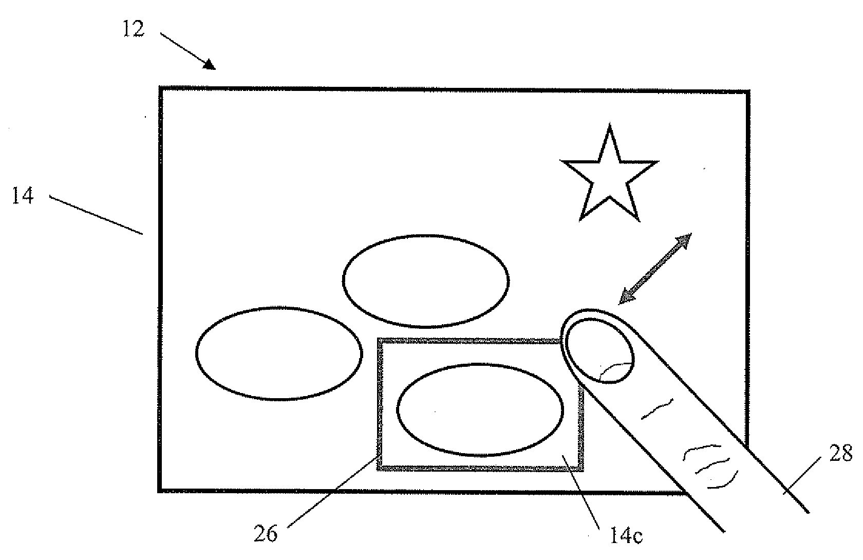
[0008]The device may provide an intuitive and user-friendly user interface for controlling an optical zoom and / or a digital zoom using a one-handed, one-touch gesture. Zooming in / out is accomplished without using control buttons and / or on-screen control icons, and the selected area of interest may not be obstructed by the hands of a user gesturing, a stylus, and / or a cursor as the user is zooming in / out.
[0010]When using a touch screen associated with an optical zoom function, a command, such as a single tap of the touch screen may—subsequently to zooming in / out—be used to focus a zoom lens on the portion of the image displayed on the touch screen, whereby zooming in / out and focusing may be carried out quickly and with facility.
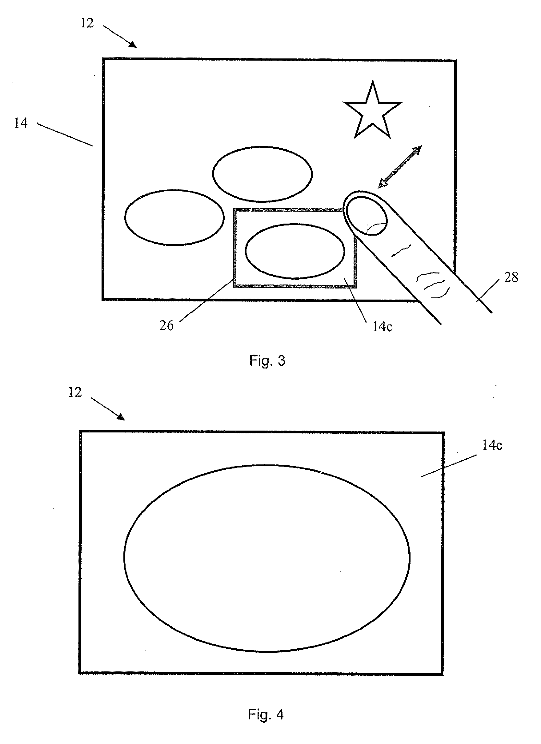
[0019]Embodiments of the present invention also may relate to a method for zooming in and / or zooming out on one or more portions of an image displayed on a display screen. The method may include a number of steps; for example, displaying an image on a display screen, determining at least one potential area of interest in the image automatically or on request, for example, automatically determining areas which a user may be interested in without the user having to provide input as to which area(s) the user is interested, highlighting at least a boundary of the at least one potential area of interest, and zooming in / zooming out the highlighted (e.g., enclosed) portion of the image when a user drags the boundary of a highlighted potential area of interest over at least portion of the display screen.

Problems solved by technology

Naturally, the use of such control buttons / icons occupies valuable, limited camera space and / or display screen space.
Additionally, onscreen control icons may obstruct a portion of the displayed image.
Such gestures may, however, obstruct part of the image being displayed while the user is zooming in / out, and gesturing may not be intuitively simple to some users or easy to perform while holding a camera steadily.

Method used


Image

  • Device, method and computer program product
  • Device, method and computer program product
  • Device, method and computer program product

Examples


Embodiment Construction

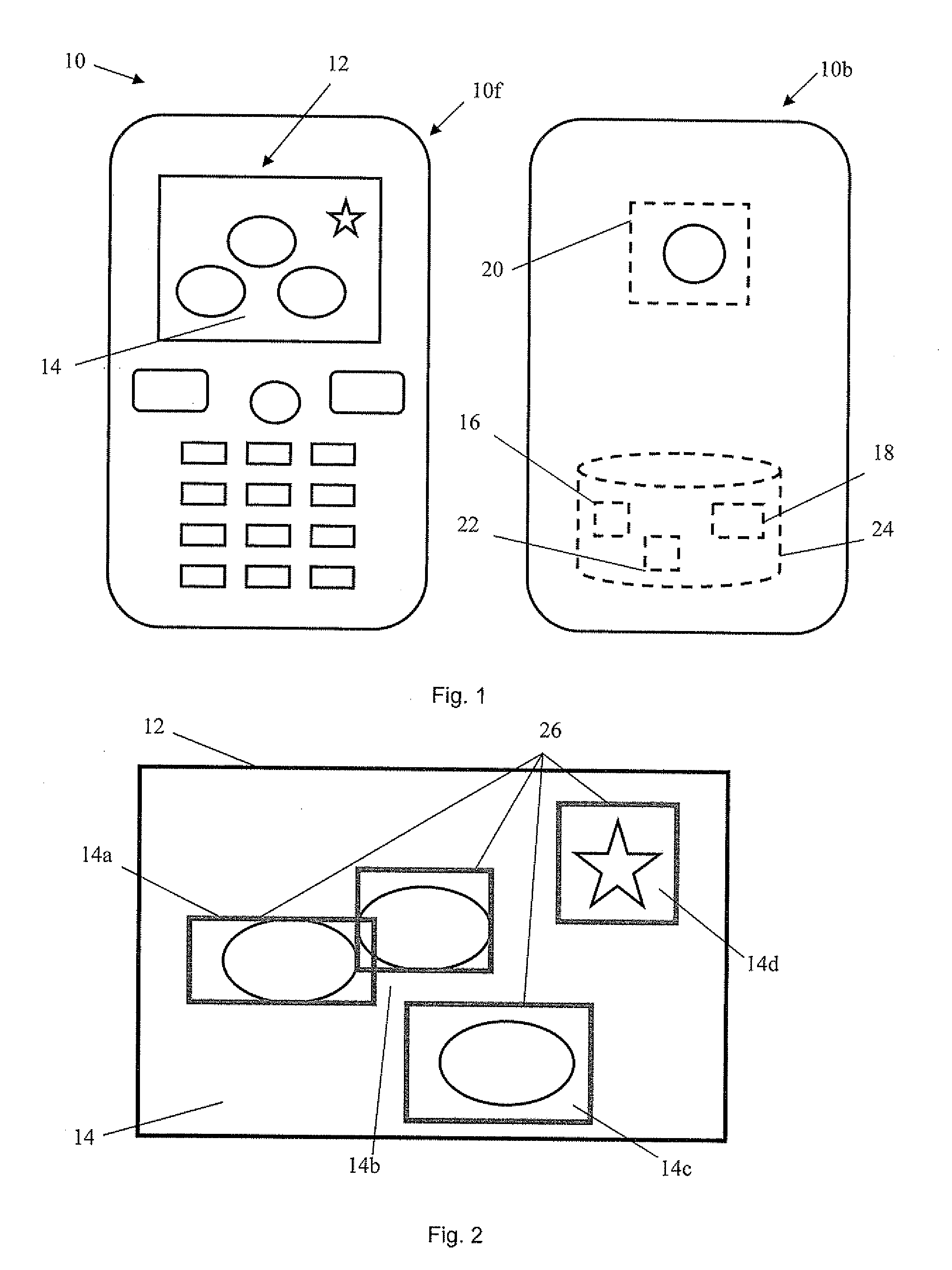
[0033]FIG. 1 shows a front 10f and a back 10b of a device 10 according to an exemplary embodiment of the invention, for example, a mobile telephone including a camera for capturing still and / or video images. Device may be any other communication and / or network apparatus. Device 10 may include a display screen 12, for example, a touch screen, for displaying an image 14 (e.g., an image that is about to be captured (e.g., recorded) or an image that has already been previously captured (e.g., stored)). Device 10 may also include an image analyzer 16 to, among other things, determine at least one potential area of interest in image 14, for example, by scanning and analyzing (displayed) image 14 for potential areas of interest using any image analysis method.

[0034]Device 10 may also comprise a visual indicator 18 that is arranged to highlight at least a boundary of the at least one potential area of interest, an optical zoom 20, and a digital zoom 22, to, for example, change the magnifica...


PUM


Abstract

A device is provided, in which a display screen displays an image; an image analyzer determines at least one potential area of interest in the image; a visual indicator highlights at least a boundary of the at least one potential area of interest, and an optical zoom and / or a digital zoom changes the magnification level of an area of interest selected from the at least one potential area of interest. The device permits a user to zoom in and / or zoom out of the selected area of interest by displacing the boundary of the selected area of interest over at least a portion of the display screen.

Description

TECHNICAL FIELD[0001]The present invention generally relates to a device including a display screen for displaying an image and, more particularly, to a method for zooming in and / or zooming out part of that image.BACKGROUND OF THE INVENTION[0002]A conventional lens in a camera works by accumulating visible light rays associated with an object, which are projected over a portion of a film or a digital camera optical sensor to form an image of the object. An optical zoom function of the camera may be used to change the magnification of the image before it is captured. A digital zoom may be used to change the magnification of an image after it has been captured.[0003]An optical zoom arrangement may include a zoom lens whose focal length, and consequently the viewing distance and field of view of the camera, can be adjusted using the camera's optics, thereby changing the magnification of a projected image. A digital zoom arrangement may crop a captured image down to centered area with t...

Claims


Application Information

Patent Timeline
IPC IPC(8): G06K9/46G06K9/32G06V10/25
CPCG06F3/04845G06F2203/0381G06F2203/04806H04N5/23296H04N5/232H04N5/23293G06K9/3233G06V10/25H04N23/635H04N23/69
Inventor THORN, KARL OLA
Owner SONY CORP
Learn More