
Magnet arrangement for generating an nmr-compatible homogeneous permanent magnetic field

a permanent magnetic field, nmr compatible technology, applied in magnetic measurements, geological measurements, reradiation, etc., can solve the problems of insignificant influence on the actual magnetic penetration depth, unusable portable use of nmr devices, etc., to achieve simple and cost-effective means, simple construction, and simple

Inactive Publication Date: 2010-09-16
FRAUNHOFER GESELLSCHAFT ZUR FOERDERUNG DER ANGEWANDTEN FORSCHUNG EV
View PDF18 Cites 5 Cited by
  • Summary
  • Abstract
  • Description
  • Claims
  • Application Information

AI Technical Summary

Benefits of technology

The invention is a refined magnet arrangement for generating an NMR-compatible homogeneous permanent magnetic field. The arrangement is variable in size and is simple, cost-effective, and robust in handling. It can be easily moved and is particularly suitable for small objects such as biological samples. The arrangement includes two main magnets with parallel magnet surface areas that create an interspace through which a homogeneous magnetic field is generated. The arrangement also includes a second magnetic field generated by the main magnets to increase the magnetic field strength and make it more uniform. The arrangement can be fixed in place using a fixing mechanism. The arrangement can be used in combination with an HF coil arrangement to generate and acquire NMR signals. The permanent magnets used in the arrangement can be made with a high field strength of at least one tesla.

Problems solved by technology

It is certainly possible to improve the penetration depth into the object to be studied by corresponding size dimensioning of the permanent magnets used, but scaling measures of this type are only capable of influencing the actual magnetic penetration depth insignificantly.
In addition, the NMR device becomes unusable for portable use due to larger and thus heavier permanent magnets.

Method used


Image

  • Magnet arrangement for generating an nmr-compatible homogeneous permanent magnetic field
  • Magnet arrangement for generating an nmr-compatible homogeneous permanent magnetic field

Examples


Embodiment Construction

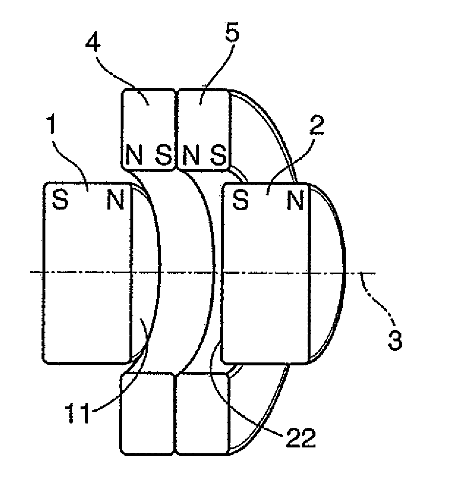
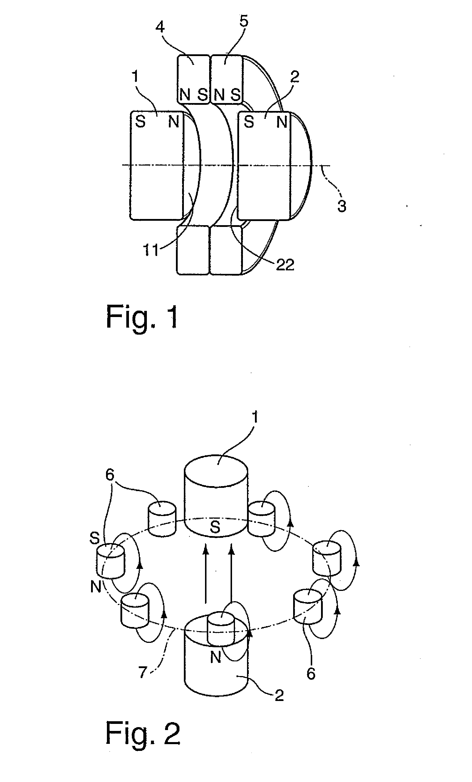
[0025]A first exemplary embodiment for implementing the permanent magnet arrangement according to the solution is shown in FIG. 1, for generating a very strong and homogeneous magnetic field without electrical components. That is, generating a magnetic field exclusively on the basis of permanent magnets, which can be used for NMR studies. The permanent magnet arrangement thus has two main magnets 1, 2, which are each implemented as solid cylindrical magnets in the illustrated exemplary embodiment. Both main magnets 1, 2 are situated coaxially along a common cylinder axis 3 in such a way that their circular front faces 11, 22 which face toward one another, are positioned to be spaced apart from one another and axially completely mutually overlapping, so that they define an otherwise cylindrical interspace on both sides.

[0026]It is to be assumed that the main magnets 1, 2 implemented as solid cylinders are mounted so they are longitudinally displaceable along their shared cylinder axi...


PUM


Abstract

A magnet arrangement for generating an NMR-compatible homogeneous permanent magnetic field is described. The invention has two permanent magnets, referred to hereafter as main magnets, which each have a magnet pole surface area. The magnet pole surface areas are situated parallel and at a distance to one another, so that the main magnets define an interspace on both sides through their magnet surface areas. The magnet pole surfaces of the main magnets each have a magnetic polarization opposite to one another. At least two annular permanent magnets are used, which are referred to hereafter as ring magnets, are situated coaxially to one another and jointly radially bound a ring inner chamber. The ring magnets are situated relative to the two main magnets in so that the ring inner chamber at least regionally encloses the interspace, and the magnetic fields of the main and ring magnets are constructively superimposed.

Description

BACKGROUND OF THE INVENTION[0001]1. Field of the Invention[0002]The invention relates to a magnet arrangement for generating an NMR-compatible homogeneous permanent magnetic field.[0003]2. Description of the Prior Art[0004]NMR-imaging methods and also corresponding devices are used, inter alia, for the nondestructive material and structural study of objects which may comprise crystalline, glassy materials or soft materials, such as elastomers, or liquids, or biological materials.[0005]A known NMR method and also a device for this purpose can be inferred from DE 199 39 626 A1, in which a transportable NMR device is described. The known device provides two permanent magnets spaced apart from one another, which are used for generating a stationary magnetic polarization field. An HF coil arrangement and two gradient coils are provided between the permanent magnets, and the latter are used for generating a magnetic gradient field superimposed on the stationary magnetic polarization field...

Claims


Application Information

Patent Timeline
Patent Type & Authority Applications(United States)
IPC IPC(8): G01R33/44
CPCG01R33/383
Inventor MANZ, BERTRAMVOLKE, FRANKBENECKE, MARTIN
Owner FRAUNHOFER GESELLSCHAFT ZUR FOERDERUNG DER ANGEWANDTEN FORSCHUNG EV
Learn More