
Airship and Vectored Propeller Drive Therefor

a propeller drive and direction control technology, applied in the direction of rigid airships, non-rigid airships, aircraft navigation control, etc., can solve the problems of heavy and cumbersome, low efficiency, high maintenance effort, etc., and achieve the effect of improving the manoeuvrability of airships

Inactive Publication Date: 2010-09-09
21ST CENTURY AIRSHIP TECH
View PDF21 Cites 12 Cited by
  • Summary
  • Abstract
  • Description
  • Claims
  • Application Information

AI Technical Summary

Benefits of technology

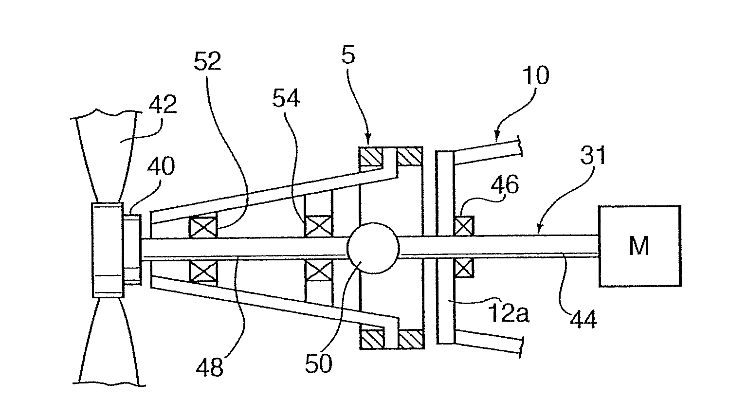
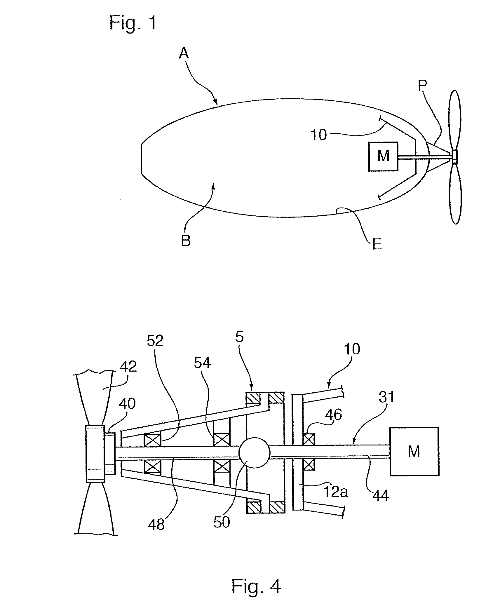
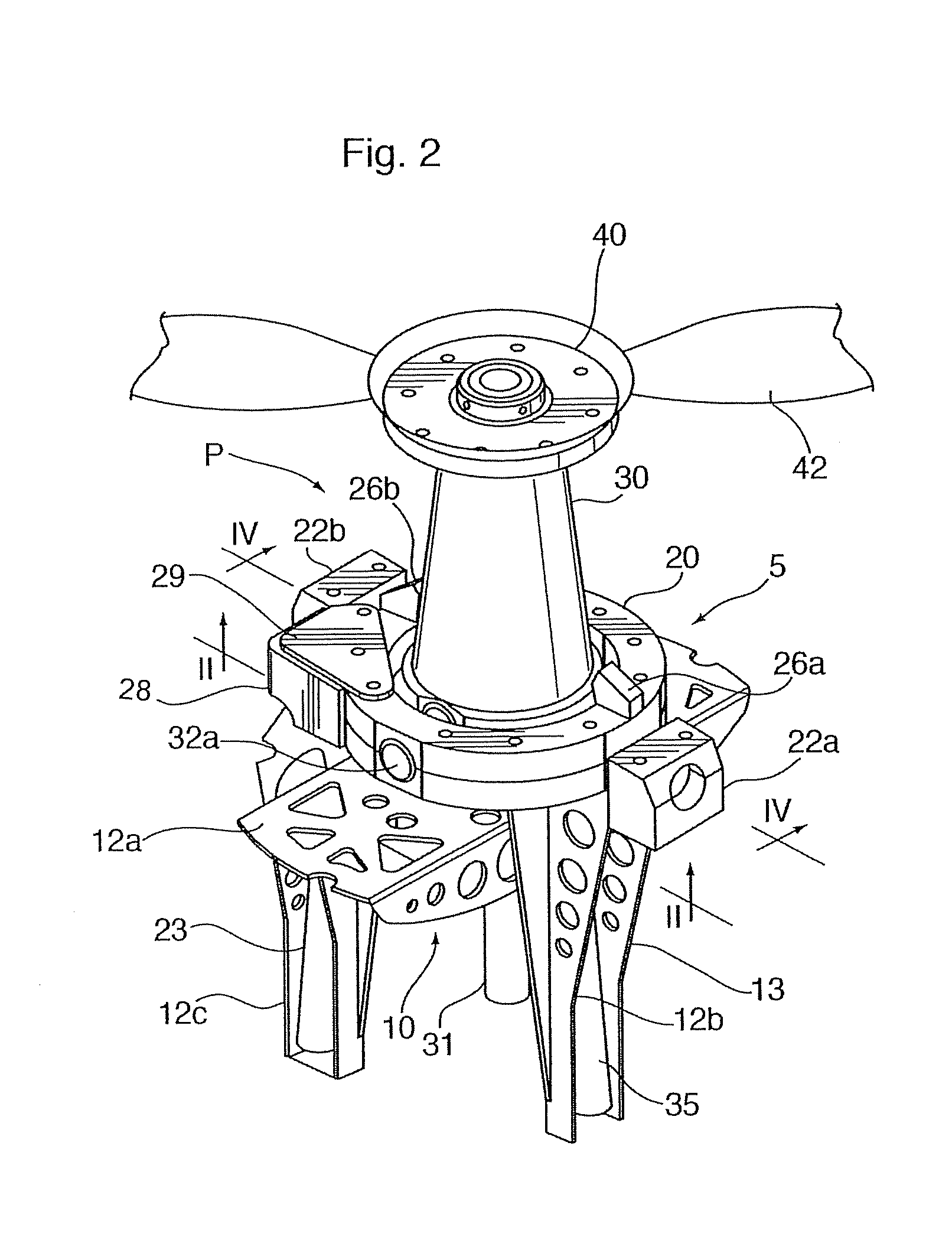
[0006]In another aspect, the invention provides an airship having an aerostatic lift body with a fuselage having at least one propulsion unit mounted thereon, the propulsion unit comprising an external driveshaft, gimbal mounted to the fuselage of the airship comprising an inner ring and an outer ring having orthogonal rotational axes, and a propeller unit comprising a conical housing pivotable on trunnions with the gimbal and a propeller affixed to a propeller shaft coaxial with the axis of the cone. Orientation of the conical housing and propeller shaft is accomplished by actuators, a first actuator being mounted between the framework and the outer ring, controlling the inclination of the outer ring relative to the framework and a second actuator being mounted between the outer ring and the conical housing, controlling the inclination of the conical housing relative to the outer ring. Preferably the airship has two propulsion units mounted fore and aft of the fuselage, although a single unit at one end of the airship enhances the manoeuvrability of the airship.

Problems solved by technology

This can become heavy and cumbersome where a large motor is needed for high power.
Various drawbacks to these apparatuses and methods include high cost, low efficiency and potentially high maintenance efforts.

Method used


Image

  • Airship and Vectored Propeller Drive Therefor
  • Airship and Vectored Propeller Drive Therefor
  • Airship and Vectored Propeller Drive Therefor

Examples


Embodiment Construction

[0014]The description that follows and the embodiments described therein are provided by way of illustration of examples of particular embodiments of the principles of the present invention. These examples are provided for the purposes of explanation, and not of limitation, of those principles and of the invention. In the description, like parts are marked throughout the specification and the drawings with the same respective reference numerals. The drawings are not necessarily to scale and in some instances proportions may have been exaggerated in order more clearly to depict certain features of the invention.

[0015]Referring to FIG. 1, an airship A includes a buoyant body B with a propulsion unit P mounted at the forward tip of the airship A. The envelope E contains a buoyant gas. The volume of gas within the envelope may be varied to adjust the buoyancy of the airship A in a well known manner that need not be described further. The body B may include an internal or external framew...


PUM


Abstract

A propulsion unit for an airship comprises a driveshaft, having a gimbal mount to a mounting frame attachable to a fuselage, the gimbal being mounted in the mounting frame and comprising an inner ring and an outer ring having orthogonal rotational axes, the inner ring including a propeller unit having a conical housing pivotable on trunnions with the gimbal and a propeller affixed to a propeller shaft coaxial with the axis of the conical housing. The outer ring includes a toroidal Orientation of the conical housing and propeller shaft is accomplished by actuators, a first actuator controlling the angle of the outer ring relative to the framework and a second actuator controlling the angle of the conical housing relative to the outer ring.

Description

CROSS REFERENCE TO RELATED APPLICATIONS[0001]This application claims priority from U.S. Application No. 61 / 149,797 filed on Feb. 4, 2009, the contents of which are incorporated herein by reference.BACKGROUND OF THE INVENTION[0002]The present invention relates generally to a direction control and propulsion system for an airship.[0003]Airships are capable of low airspeeds right down to motionless hovering, and at such speeds must depend upon means other than rudders, ailerons and similar air-deflecting panels to control their direction and attitude in flight and hovering. One conventional method of gaining such control has been by using a propulsion unit having a propeller and propulsion motor mounted on a movable platform, the angle of the combination being variable in pitch and yaw. This can become heavy and cumbersome where a large motor is needed for high power. Another method has been to mount motor-propeller units on vertical shafts under the airship and to rotate the units on ...

Claims


Application Information

Patent Timeline
IPC IPC(8): B64B1/30
CPCB64B1/30
Inventor COLTING, HOKAN S.
Owner 21ST CENTURY AIRSHIP TECH
Learn More