Microphone module for a hearing device

a technology for hearing devices and microphones, applied in the direction of deaf-aid sets, electric devices, etc., can solve the problems of structure-borne sound and feedback suppression at the microphones, and achieve the effect of avoiding feedback and being advantageously used

Inactive Publication Date: 2010-08-19
SIEMENS MEDICAL EQUIPMENT
View PDF4 Cites 16 Cited by
  • Summary
  • Abstract
  • Description
  • Claims
  • Application Information

AI Technical Summary

Benefits of technology

[0008]An object of the present invention is to better damp the structure-borne sound in hearing devices with high amplification.
[0010]Through the module housing, the microphone advantageously can be additionally decoupled from the housing of the hearing device. High amplifications can thus be employed with little danger of feedback.
[0013]According to a further embodiment, the module housing is hermetically sealed, other than from respective sound inlet openings for each microphone. This is in particular advantageous if the microphone module is installed in a hearing aid or another hearing device and, due to the seal, no sound penetrates into the internal components of the module housing and to the microphones via unintentional paths.
[0015]In particular, the microphone pouch can have a sound conduction nozzle (connector) in order to conduct sound from a sound inlet opening of the module housing to an opening in the microphone housing. Such a sound inlet nozzle can provide advantages by transmitting the sound optimally undisturbed to the respective microphone.
[0016]Furthermore, the mounting device can have multiple rubber nubs that can be plugged into or onto the housing of the hearing device. A robust and installation-friendly mounting (support) of the microphone module can be achieved in this way.
[0017]The microphone module can be particularly advantageously used in a hearing device that is fashioned as a hearing aid. The danger of feedback is markedly reduced by a microphone module of this design in a hearing device.

Problems solved by technology

Since amplifications of 80 dB and more are required in certain hearing devices, the structure-borne sound and feedback suppression at the microphones is one of the main problems in satisfying these high demands.

Method used


Image

  • Microphone module for a hearing device
  • Microphone module for a hearing device
  • Microphone module for a hearing device

Examples


Embodiment Construction

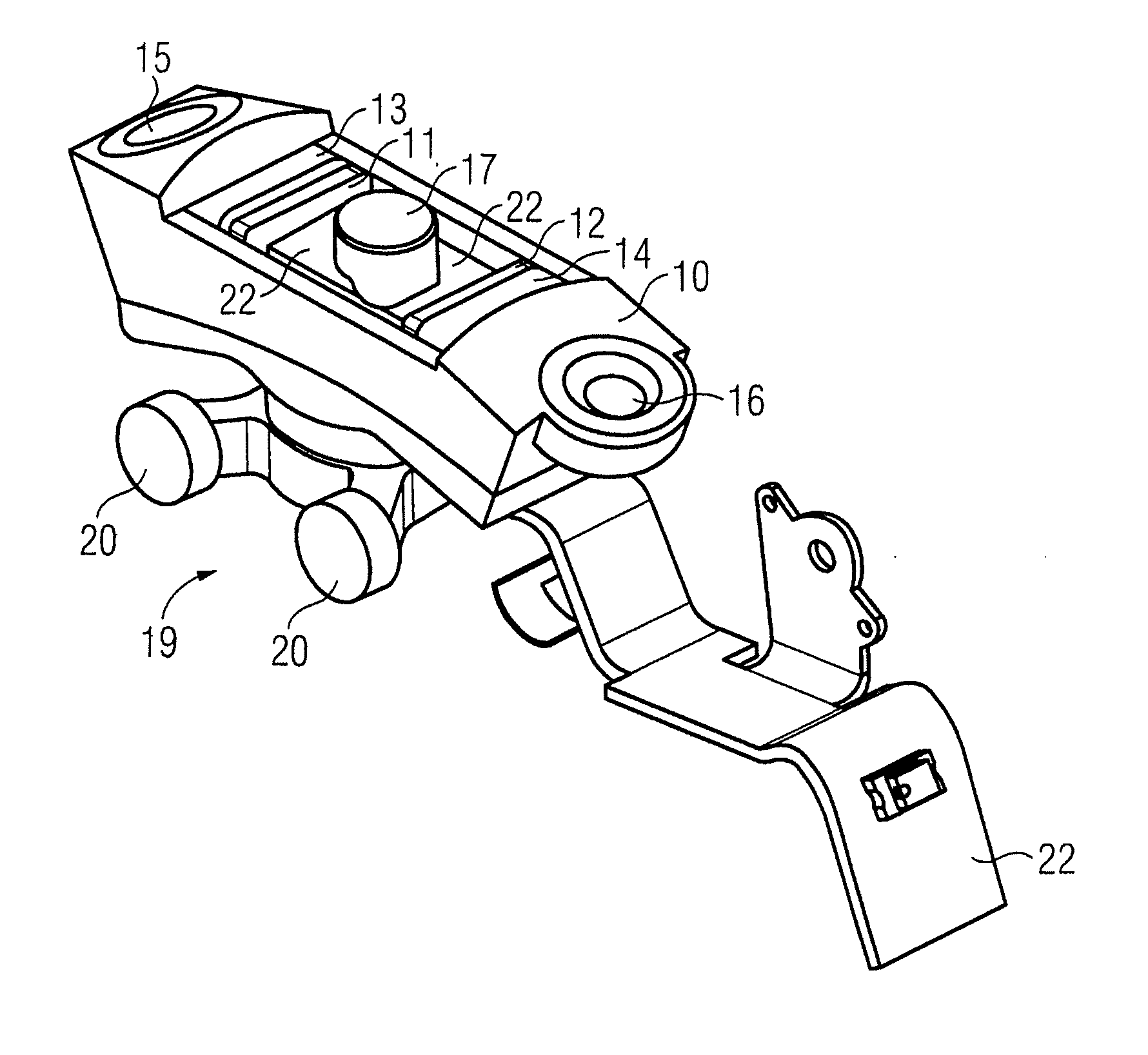
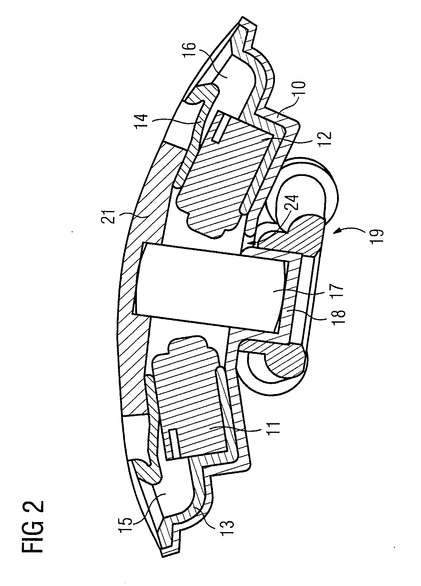
[0023]The microphone module shown in FIG. 2 represents a separate (stand-alone) unit that can be easily installed in a hearing device housing or can be easily removed from the hearing device housing. It has a stand-alone module housing 10 in which here are accommodated two microphones 11, 12. The microphones 11, 12 are mounted (carried) in the module housing 10 by microphone pouches 13, 14. The module pouches 13, 14 respectively have a sound conduction nozzles 15, 16. The sound to be received penetrates from the outside to the microphones 11, 12 via these sound conduction nozzles 15, 16. To damp structure-borne sound, the microphone pouches 13, 14 are produced from a soft material, for example rubber or foamed rubber. The housing of the microphones 11, 12 does not directly contact the module housing 10. Structure-borne thus sound can only arrive from the module housing 10 to the microphone housings or the microphones 11, 12 via the microphone pouches 13, 14.

[0024]Furthermore, an ind...


PUM


Abstract

A better decoupling of the microphones of a hearing device from the housing of the hearing device is achieved by a microphone module having a module housing that is not part of the housing of the hearing device, and at least one microphone including a microphone housing that is arranged in the module housing. Furthermore, the microphone module has a mounting device that elastically supports the module housing in the housing of the hearing device. The microphone module can additionally have an inductive receiver, for example, and / or can be connected with a flexible circuit board to the remaining electronics of the hearing aid or the hearing device.

Description

BACKGROUND OF THE INVENTION[0001]1. Field of the Invention[0002]The present invention concerns a microphone module for a hearing device. As used herein, a hearing device means any sound-outputting device (in particular a hearing aid, a headset, headphones and the like) that can be worn in or on the ear or on the head.[0003]2. Description of the Prior Art[0004]Hearing aids are wearable hearing devices that serve to assist the hard of hearing. In order to accommodate numerous individual needs, different structural shapes of hearing devices are provided, such as behind-the-ear hearing devices (BtE), hearing devices with external earpiece (RIC: receiver in the canal) and in-the-ear hearing devices (ItE), as well as concha hearing devices or canal hearing devices, for example (ITE, CIC). The hearing devices listed as examples are worn on the outer ear or in the auditory canal. Moreover, however, bone conduction hearing devices, implantable or vibro-tactile hearing devices are available o...

Claims


Application Information

Patent Timeline
IPC IPC(8): H04R25/00
CPCH04R25/405H04R25/604H04R25/456H04R25/554
Inventor RITTER, HARTMUTSATTLER, MICHAEL
Owner SIEMENS MEDICAL EQUIPMENT
Why Eureka
Try Eureka