
Feeding device and image recording apparatus with the feeding device

a technology of feeding device and image recording apparatus, which is applied in the direction of electrographic process, instruments, transportation and packaging, etc., can solve the problems of downsizing of feeding device or image recording apparatus with feeding device, and achieve the effect of less damag

Active Publication Date: 2010-08-19
BROTHER KOGYO KK
View PDF6 Cites 29 Cited by
  • Summary
  • Abstract
  • Description
  • Claims
  • Application Information

AI Technical Summary

Benefits of technology

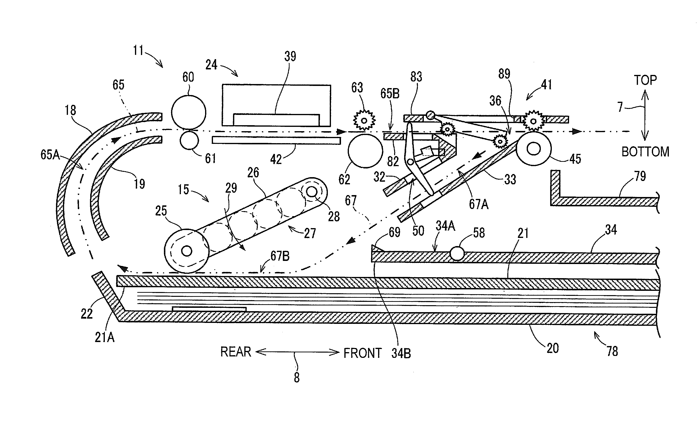
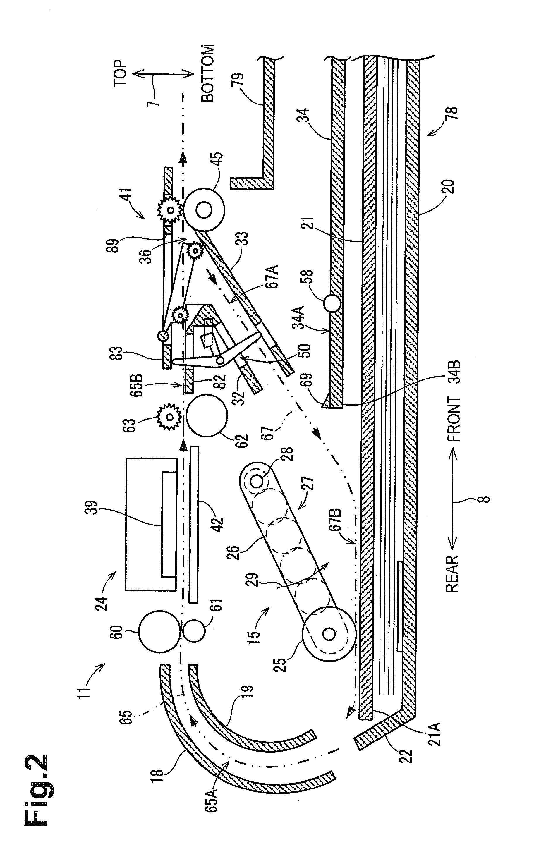
[0007]It is an object of the present invention to provide a downsized feeding device and an image recording apparatus with the feeding device, which is capable of switching the traveling direction of the sheet with less damage to the trailing end of the sheet which is reversed and becomes a new leading end of the sheet, and in which the distance from the rotating member to the reversing roller is short.
[0010]According to the feeding device and the image recording apparatus with the feeding device of the present invention, damage to the trailing end of the sheet which is reversed and becomes a new leading end of the sheet can be reduced. Furthermore, since the distance from the rotating member to the reversing roller is short, the feeding device or the image recording apparatus with the feeding device can be downsized.

Problems solved by technology

Furthermore, since the distance from the rotating member to the reversing roller is short, the feeding device or the image recording apparatus with the feeding device can be downsized.

Method used


Image

  • Feeding device and image recording apparatus with the feeding device
  • Feeding device and image recording apparatus with the feeding device
  • Feeding device and image recording apparatus with the feeding device

Examples


Embodiment Construction

[0024]Referring to the drawings, preferred embodiments of the present invention will be described below. Note that the embodiments described below are merely examples of the present invention, and the embodiments of the present invention can of course be modified within the scope not changing the gist of the present invention.

[0025][Outline of the Multifunction Device]

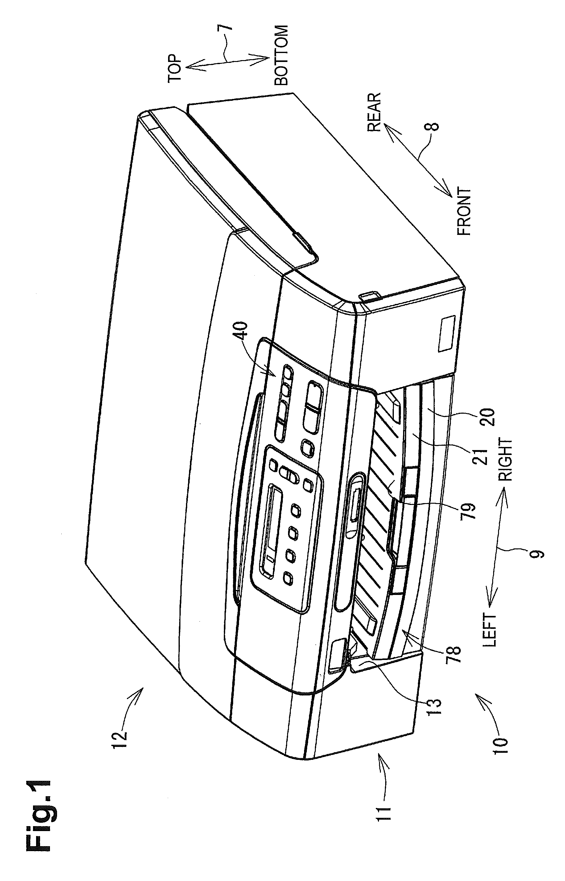
[0026]FIG. 1 is a perspective view showing the exterior of a multifunction device 10 according to an embodiment of the present invention. In the following description, a top-bottom direction 7 is defined based on a state in which the multifunction device 10 is installed in a usable state (the state shown in FIG. 1), a front-rear direction 8 is defined such that the side having an operation panel 40 is the near side (front), and a left-right direction 9 is defined by viewing the multifunction device 10 from the near side (front).

[0027]The multifunction device 10 has a substantially thin rectangular parallelepiped shape,...


PUM

PropertyMeasurementUnit
sizesaaaaaaaaaa
sizesaaaaaaaaaa
sizeaaaaaaaaaa

Abstract

A feeding device includes a conveying roller that conveys a sheet downstream when the conveying roller rotates forward. A first guide member guides the conveyed sheet toward the conveying roller. A second guide member guides the sheet when the conveying roller rotates in reverse. A rotating member is positioned between the first guide member and the conveying roller, and has a support shaft and a pressing portion. The rotating member rotates about the support shaft between a first supported state where the rotating member is separated from the second guide member, and a second supported state where the rotating member is closer to the second guide member. In the first supported state, the sheet is conveyed from the first guide member to the conveying roller. A trailing end of the sheet moves toward the second guide member when the rotating member transitions from the first to the second supported state.

Description

CROSS REFERENCE TO RELATED APPLICATION[0001]The present application claims priority from Japanese Patent Application No. 2009-032879, which was filed on Feb. 16, 2009, the disclosure of which is incorporated herein by reference in its entirety.BACKGROUND OF THE INVENTION[0002]1. Field of the Invention[0003]The present invention relates to a feeding device and an image recording apparatus having a mechanism for sending a sheet with an image recorded on one side thereof back to the recording unit.[0004]2. Description of the Related Art[0005]Conventionally, feeding devices capable of switching the traveling direction of the sheet to feed to another path are known. In such a feeding device, a rotating member rotates after a trailing end of the sheet conveyed in a first conveying path has passed through, the traveling direction is switched, and the trailing end of the sheet, which is reversed and becomes a new leading end of the sheet, contacts the rotated rotating member to be guided to...

Claims


Application Information

Patent Timeline
Patent Type & Authority Applications(United States)
IPC IPC(8): B65H5/26B65H5/06
CPCB65H5/36B65H2801/06B65H2301/33312B65H85/00
Inventor SAMOTO, KENJIKOGA, YUJI
Owner BROTHER KOGYO KK
Learn More