
Wireless station and wireless LAN system

a wireless lan and wireless technology, applied in the field of wireless lan systems, can solve the problems of increasing the troublesome task of remote setup described above, and the complexity of adjusting the settings through the user interface, so as to load the task of wireless lan settings on users

Inactive Publication Date: 2010-08-12
BROTHER KOGYO KK
View PDF45 Cites 15 Cited by
  • Summary
  • Abstract
  • Description
  • Claims
  • Application Information

AI Technical Summary

Benefits of technology

[0017]The present invention is advantageous in that the load of the task of wireless LAN settings on users as described above can be reduced.
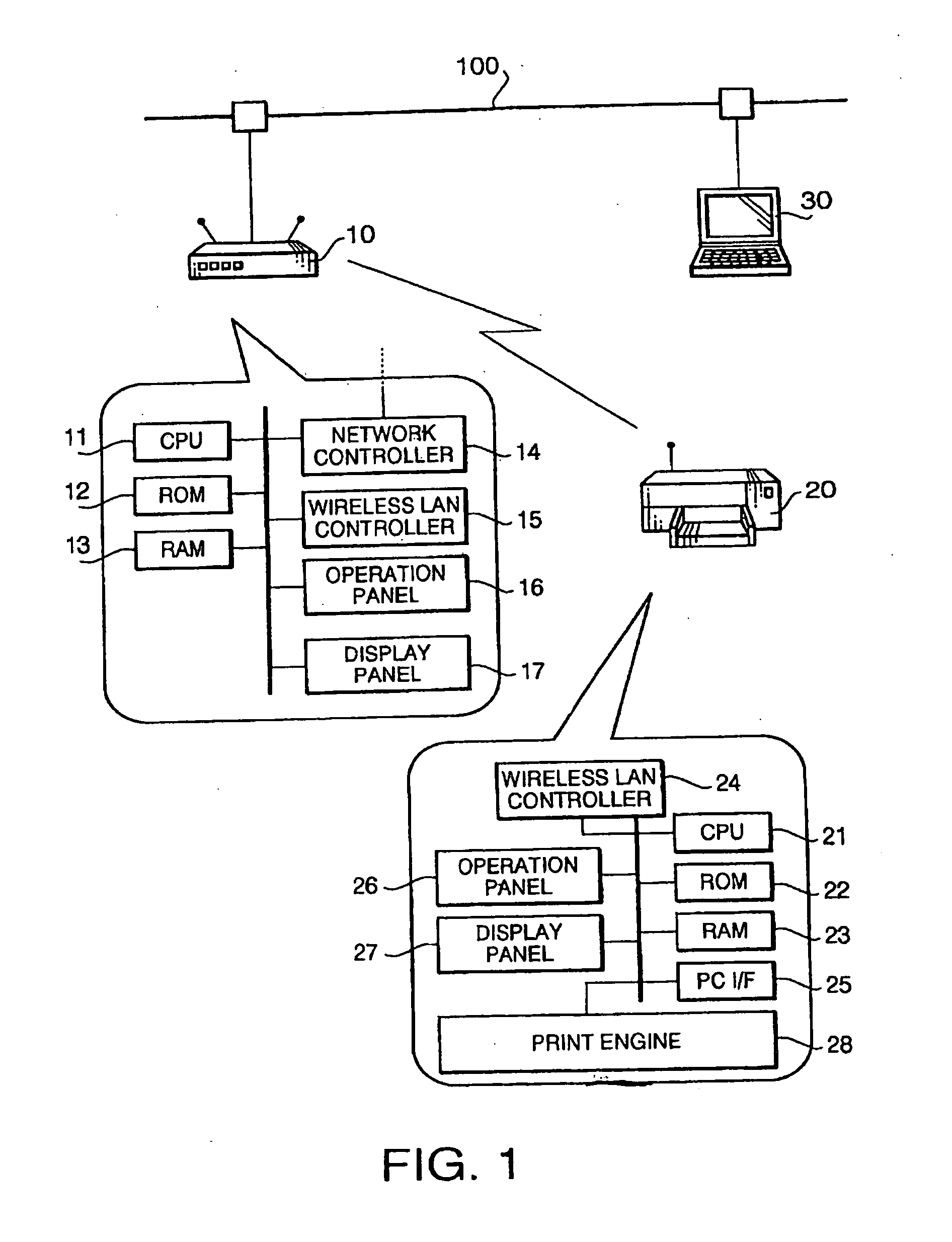
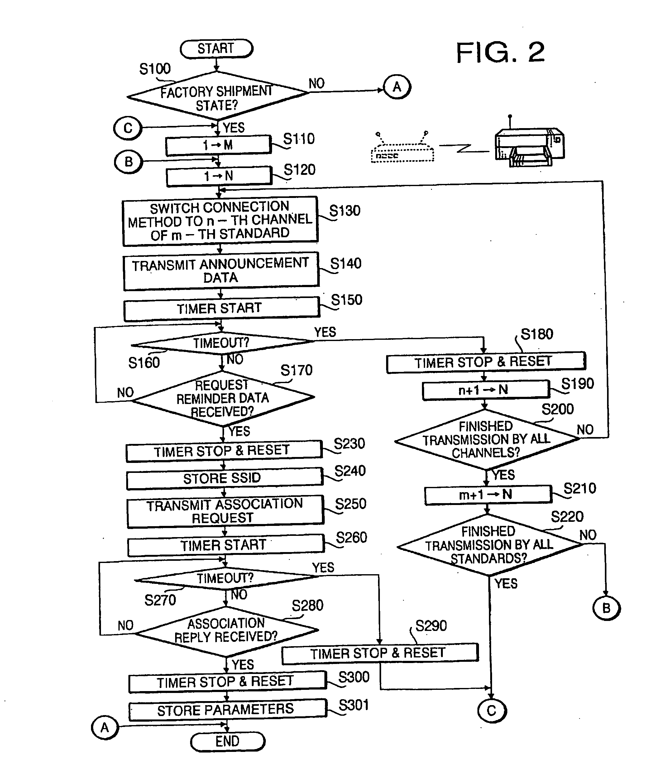
[0105]In this composition, the length of the period in which the method switching system switches the connection method from the preset connection method should be as short as possible, as long as time necessary for the transmission of the announcement data can be secured. During the period in which the connection method is changed from the preset connection method, the wireless access point generally can not carry out data communication which should be conducted according to the preset connection method. Therefore, the shortness of the period (in which the connection method is changed) is advantageous for avoiding the inconvenience of the interruption of data communication which should be conducted according to the preset connection method.
[0112]Such setting of the connection method (for the connection to the wireless access point) specified by the announcement data having the highest reception level is advantageous for preventing erroneous setting of the connection method of the wireless station to a false connection method different from the method for the connection to the correct wireless access point.

Problems solved by technology

However, with wireless stations equipped with a user interface of lower operability compared to that of a PC (e.g. printers providing services via a network), adjusting the settings through the user interface becomes an extremely complex and troublesome task.
However, even the remote setup described above is still a troublesome task to the user since the user is required to move the wireless stations (after switching the communication method to the “ad hoc mode”) to positions allowing wireless communication or to move the PC to a position allowing the direct connection to the wireless station by a cable.
Especially when a wireless station which has been used in the “infrastructure mode” is employed for the remote setup, the user has to return the communication method of the wireless station from the “ad hoc mode” to the “infrastructure mode” after the remote setup is finished, which makes the task more troublesome.
As described above, in cases of wireless stations equipped with a user interface of lower operability compared to that of a PC (e.g. printers providing services via a network), the adjustment of the settings through the user interface takes time and trouble.
Since the wireless LAN settings require a wide range of expertise, even users with technical knowledge of wired LAN can not necessarily adjust the wireless LAN settings with ease.
Thus, the adjustment of wireless LAN settings is extremely difficult for users unfamiliar with LAN itself.
As described above, the task of wireless LAN settings is presently a heavy load on the user and it is regarded as a factor blocking the prevalence of wireless LAN.

Method used


Image

  • Wireless station and wireless LAN system
  • Wireless station and wireless LAN system
  • Wireless station and wireless LAN system

Examples


embodiment 1

Modification of Embodiment 1

[0278]The first embodiment can also be implemented with part of its composition altered to other composition as shown below. Incidentally, the composition shown below is also applicable to similar parts of other embodiments.

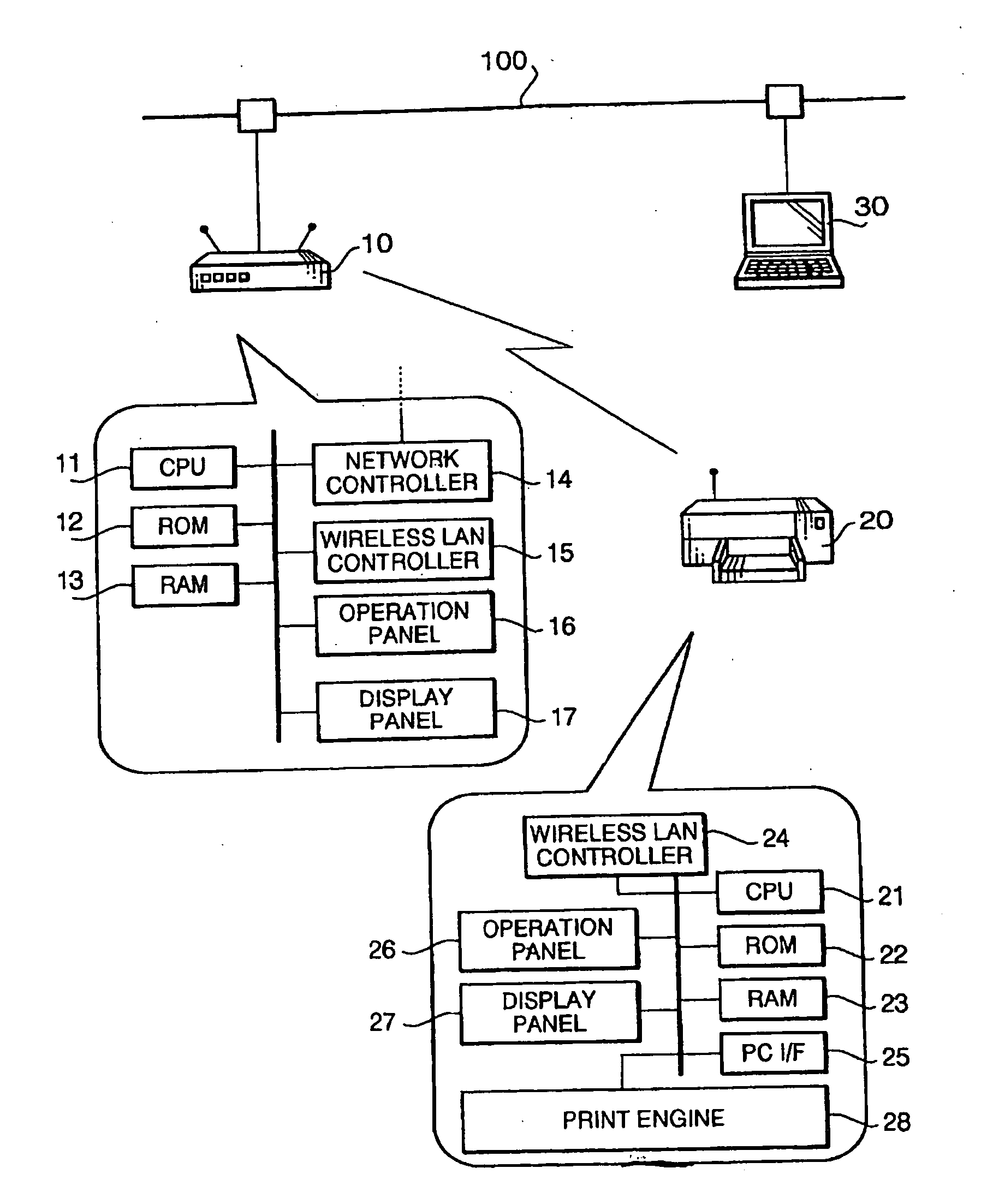
[0279]For example, while the process from the step S110 is executed only when the printer 20 is in its factory shipment state (S100 of FIG. 3), it is also possible to configure the printer 20 to execute the process from the step S110 even if it is not in the factory shipment state, in cases where the setting of the connection method is necessary (e.g. when part of the “parameters indicating the connection method” stored in the ROM 22 is lacking).

[0280]While the association request and association reply are exchanged after the exchange of the authentication request and authentication reply in the above embodiment, it is also possible to omit the authentication request / reply and carry out the exchange of the association request / reply onl...

embodiment 2

Modification of Embodiment 2

[0309]The second embodiment can also be implemented with part of its composition altered to other composition as shown below. Incidentally, the composition shown below is also applicable to similar parts of other embodiments.

[0310]For example, while the step S570 judges whether or not the reception level in the parameters registered regarding the received announcement data is the highest reception level among all the parameters, the step S570 may also be configured to judge whether or not the device ID in the parameters registered regarding the received announcement data is identical with the device ID at the point of the reception of the announcement data in the step S540. In this case, even when the same announcement data as the registered announcement data is received, the access point 10 cancels the transmission of the request reminder data and the setting of the connection method if the device ID specified by the received announcement data is not ide...

embodiment 3

Modification of Embodiment 3

[0321]The third embodiment can also be implemented with part of its composition altered to other composition as shown below. Incidentally, the composition shown below is also applicable to similar parts of other embodiments.

[0322]For example, while the selection operation in the steps S512 and S514 of FIG. 7 is carried out by the user based on device names, the selection operation may also be conducted based on device IDs instead of the device names. In this case, the connection method can be set only to wireless station(s) having the device ID(s) arbitrarily selected by the user.

Embodiment 4

[0323]A wireless LAN system in accordance with a fourth embodiment of the present invention is composed similarly to the system of the third embodiment. The fourth embodiment is configured so that the notification of device names and the selection operation (steps S512 and S514) carried out by the access point 10 in the third embodiment can be executed by a commonly ...


PUM


Abstract

A wireless LAN system in which data communication between a wireless station whose connection method as a method for wireless connection can be set to one of a plurality of connection methods and a wireless access point whose connection method has been preset to one of the connection methods is made possible by setting the connection method of the wireless station to a method identical with the connection method of the wireless access point.

Description

INCORPORATION BY REFERENCE [0001]This is a Division of Application No. 10 / 969,066 filed Oct. 21, 2004, which in turn claims priority of Japanese Applications No. 2003-362230 filed Oct. 22, 2003, 2003-362231, filed Oct. 22, 2003 and 2003-262232, filed Oct. 22, 2003. The disclosure of the prior applications is hereby incorporated by reference herein in its entirety.BACKGROUND OF THE INVENTION[0002]The present invention relates to a wireless LAN system in which data communication between a wireless access point and a wireless station is made possible by setting the connection method of the wireless station to a method identical with the connection method of the wireless access point, a communication terminal usable in the wireless LAN system, and a communication program.[0003]Nowadays, the so-called wireless LANs, realizing data communication among a plurality of wireless stations or data communication between a wireless station and an external network by use of radio waves, have becom...

Claims


Application Information

Patent Timeline
Patent Type & Authority Applications(United States)
IPC IPC(8): H04W40/00G06F3/12H04L12/28H04L12/56H04L29/06
CPCG06F3/1203H04W88/06G06F3/1226G06F3/1236G06F3/1285G06F3/1292H04L63/0442H04L63/0823H04W12/02H04W12/06H04W28/18H04W76/02H04W84/12H04W84/18G06F3/1204H04W76/10H04W12/037H04W28/0215H04W60/04
Inventor MATSUDA, MAKOTOOHARA, KIYOTAKATAGAWA, NORIO
Owner BROTHER KOGYO KK
Learn More