Eureka AIR delivers breakthrough ideas for toughest innovation challenges, trusted by R&D personnel around the world.

Photographing optical lens assembly

Active Publication Date: 2010-08-12
LARGAN PRECISION
View PDF3 Cites 11 Cited by
  • Summary
  • Abstract
  • Description
  • Claims
  • Application Information

AI Technical Summary

Benefits of technology

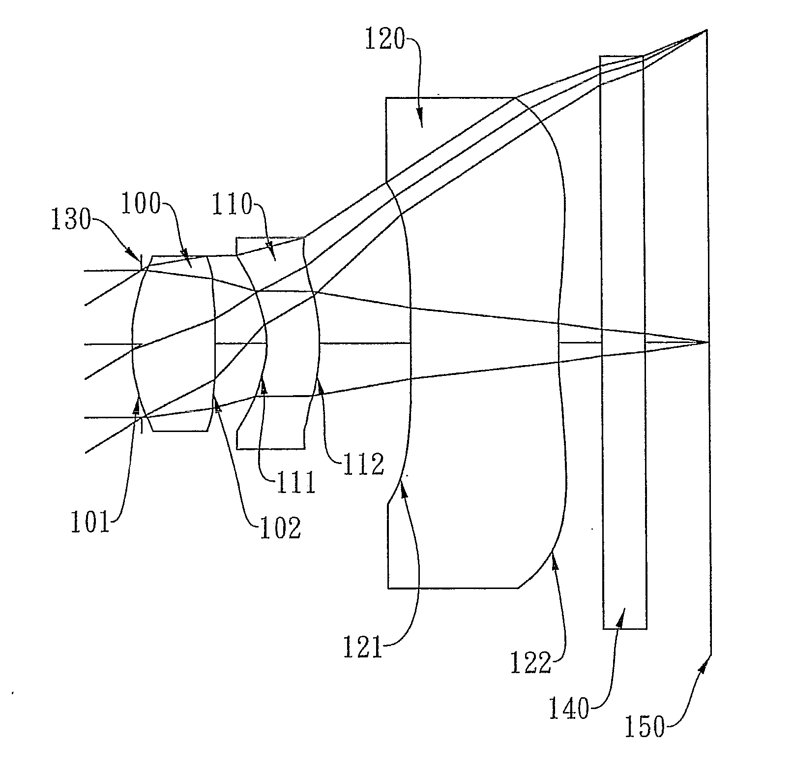
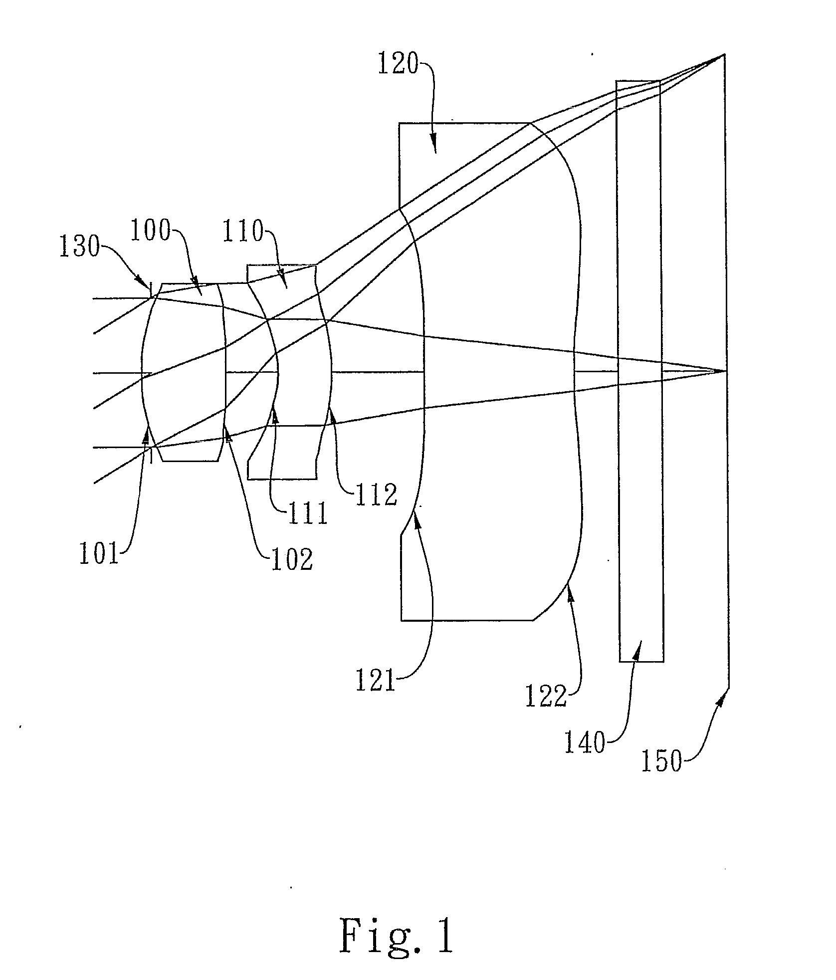
[0005]The present invention provides a photographing optical lens assembly comprising, in order from the object side to the image side: a first lens element with positive refractive power; a second lens element with negative refractive power having a concave object-side surface and a convex image-side surface, the object-side and image-side surfaces thereof being aspheric; and a third lens element with negative refractive power and at least one inflection point formed thereon having a concave object-side surface and a concave image-side surface, the object-side and image-side surfaces thereof being aspheric. Such an arrangement of optical elements can effectively correct the aberrations of the photographing optical lens assembly, improving image quality and enabling the photographing optical lens assembly to maintain a compact form.
[0006]In the present photographing optical lens assembly, the first lens element may be a bi-convex lens element or a meniscus lens element having a convex object-side surface and a concave image-side surface. When the first lens element is a bi-convex lens element, the refractive power thereof may be significantly enhanced, thus allowing a shortening of the total track length of the photographing optical lens assembly. When the first lens element is a meniscus lens element, the astigmatism of the photographing optical lens assembly may be better corrected. In addition, the third lens element has negative refractive power with a concave object-side surface and a concave image-side surface, enabling the principal point of the photographing optical lens assembly to be positioned far away from the image plane, which is favorable for shortening the total track length and maintaining a compact form.
[0008]The above relation improves the moldability and homogeneity of the plastic-injection-molded lenses and enables the total track length of the photographing optical lens assembly to be reduced effectively.
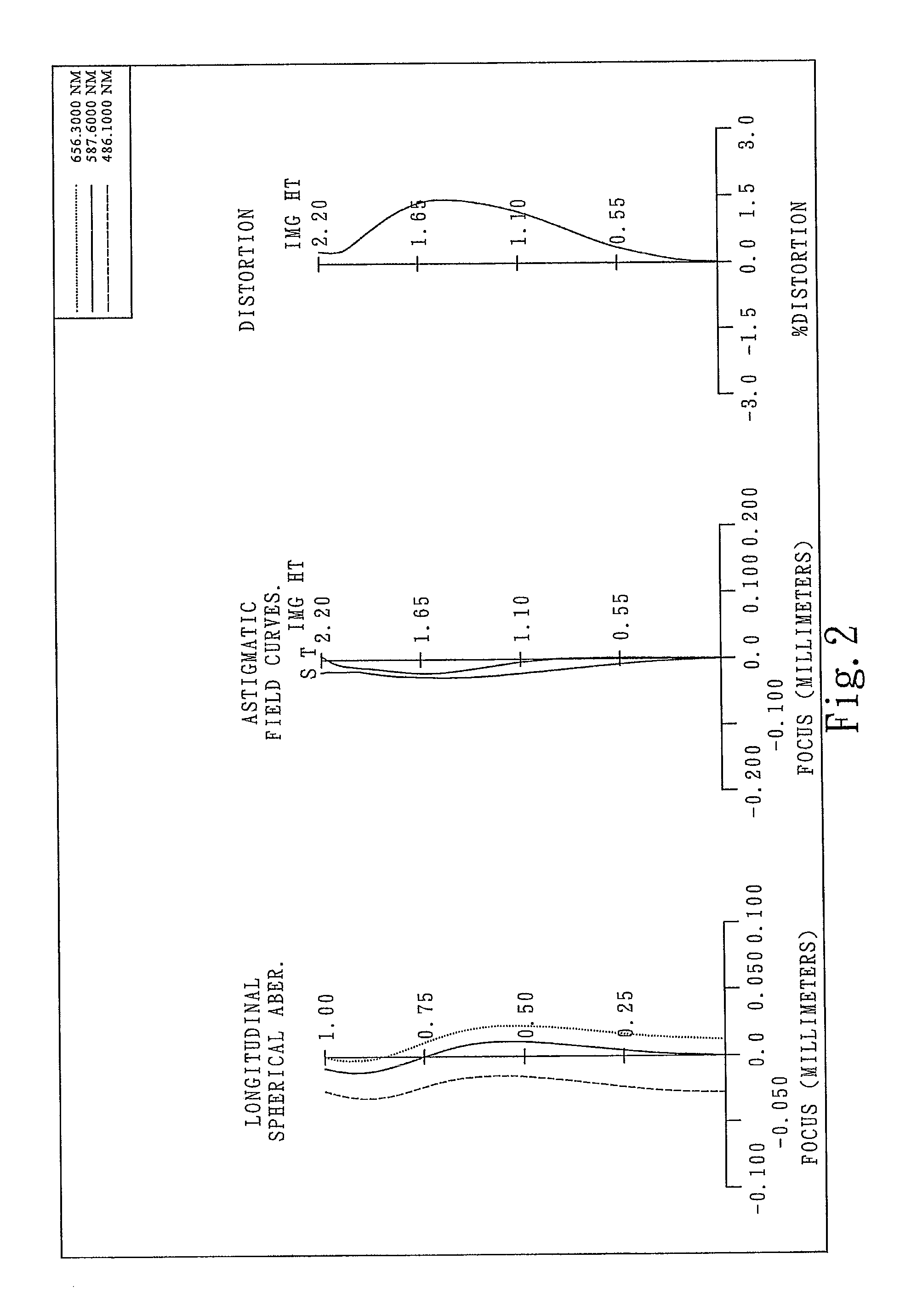
[0010]The above relation facilitates the correction of the astigmatism of the photographing optical lens assembly, so that the image quality of the photographing optical lens assembly can be improved.
[0012]The above relation facilitates the correction of the spherical aberration of the photographing optical lens assembly.

Problems solved by technology

However, with an increasing demand for compact lens assemblies featuring higher resolution and better image quality, the two-lens structure has become insufficient for a more high-end photographing lens assembly.
Therefore, the total track length of the optical lens system for taking image must also become longer to accommodate the optical track, making it difficult to meet the requirements of a more compact photographing lens assembly.

Method used


Image

  • Photographing optical lens assembly
  • Photographing optical lens assembly
  • Photographing optical lens assembly

Examples


first embodiment

[0094]In the present photographing optical lens assembly, the focal length of the first lens element 100 is f1, the focal length of the second lens element 110 is f2, the focal length of the third lens element 120 is f3, the focal length of the photographing optical lens assembly is f, and they satisfy the relations: f / f1=1.60, f / f2=−0.40, f / f3=−0.53.

[0095]In the first embodiment of the present photographing optical lens assembly, the radius of curvature of the object-side surface 101 of the first lens element 100 is R1, the radius of curvature of the image-side surface 102 of the first lens element 100 is R2, the radius of curvature of the object-side surface 121 of the third lens element 120 is R5, the radius of curvature of the image-side surface 122 of the third lens element 120 is R6, and they satisfy the relations: ≡R1 / R2|=0.04, R5 / R6=−8.51.

[0096]In the first embodiment of the present photographing optical lens assembly, the on-axis thickness of the second lens element 110 is ...

second embodiment

[0103]In the present photographing optical lens assembly, the focal length of the first lens element 300 is f1, the focal length of the second lens element 310 is f2, the focal length of the third lens element 320 is f3, the focal length of the photographing optical lens assembly is f, and they satisfy the relations: f / f1=1.96, f / f2=−0.61, f / f3=−0.80.

[0104]In the second embodiment of the present photographing optical lens assembly, the radius of curvature of the object-side surface 301 of the first lens element 300 is R1, the radius of curvature of the image-side surface 302 of the first lens element 300 is R2, the radius of curvature of the object-side surface 321 of the third lens element 320 is R5, the radius of curvature of the image-side surface 322 of the third lens element 320 is R6, and they satisfy the relations: R1 / R2=|0.72|, R5 / R6=−6.94.

[0105]In the second embodiment of the present photographing optical lens assembly, the on-axis thickness of the second lens element 310 i...

third embodiment

[0112]In the present photographing optical lens assembly, the focal length of the first lens element 500 is f1, the focal length of the second lens element 510 is f2, the focal length of the third lens element 520 is f3, the focal length of the photographing optical lens assembly is f, and they satisfy the relations: f / f1=1.59, f / f2=−0.33, f / f3=−0.64.

[0113]In the third embodiment of the present photographing optical lens assembly, the radius of curvature of the object-side surface 501 of the first lens element 500 is R1, the radius of curvature of the image-side surface 502 of the first lens element 500 is R2, the radius of curvature of the object-side surface 521 of the third lens element 520 is R5, the radius of curvature of the image-side surface 522 of the third lens element 520 is R6, and they satisfy the relations: |R1 / R2|=0.07, R5 / R6=−2.08.

[0114]In the third embodiment of the present photographing optical lens assembly, the on-axis thickness of the second lens element 510 is ...


PUM


Abstract

This invention provides a photographing optical lens assembly including, in order from an object side to an image side: a first lens element with positive refractive power; a second lens element with negative refractive power having a concave object-side surface and a convex image-side surface, the object-side and image-side surfaces thereof being aspheric; and a third lens element with negative refractive power having a concave object-side surface, a concave image-side surface and at least one inflection point formed on the third lens element, the object-side and image-side surfaces thereof being aspheric. The first lens element may be a bi-convex lens element or a convex-concave meniscus lens element. When the first lens element is a bi-convex lens element, the refractive power thereof may be significantly enhanced to shorten the total track length of the optical system. When the first lens element is a meniscus lens element, the astigmatism of the optical system may be better corrected. Such an arrangement of optical elements can effectively correct the aberrations of the optical system, improving image quality and enabling the optical lens assembly to maintain a compact form.

Description

BACKGROUND OF THE INVENTION[0001]1. Field of the Invention[0002]The present invention relates to a photographing optical lens assembly, and more particularly, to a compact photographing optical lens assembly used in a mobile phone camera.[0003]2. Description of the Prior Art[0004]A conventional compact lens assembly for mobile phone cameras, such as the optical lens system for taking image disclosed in U.S. Pat. No. 7,436,604, generally comprises two lens elements. However, with an increasing demand for compact lens assemblies featuring higher resolution and better image quality, the two-lens structure has become insufficient for a more high-end photographing lens assembly. The optical lens system for taking image disclosed in U.S. Pat. No. 7,436,603 provides a three lens element structure, a so-called triplet lens design and comprises, from the object side to the image side: a first lens element with positive refractive power; a second lens element with negative refractive power; a...

Claims


Application Information

Patent Timeline
IPC IPC(8): G02B9/12
CPCG02B13/18G02B13/04
Inventor TANG, HSIANG-CHITSAI, TSUNG-HAN
Owner LARGAN PRECISION
Why Eureka
Eureka Blog
Learn More