
Apparatus, system and method for fluid delivery

a fluid delivery and apparatus technology, applied in the field of apparatus, system and method of fluid delivery, can solve the problems of difficult patient maintenance of desired schedule, high malfunction rate, and many potentially valuable medicines or compounds, including biologicals, that are not orally active,

Active Publication Date: 2010-08-05
DEKA PROD LLP
View PDF17 Cites 105 Cited by
  • Summary
  • Abstract
  • Description
  • Claims
  • Application Information

AI Technical Summary

Benefits of technology

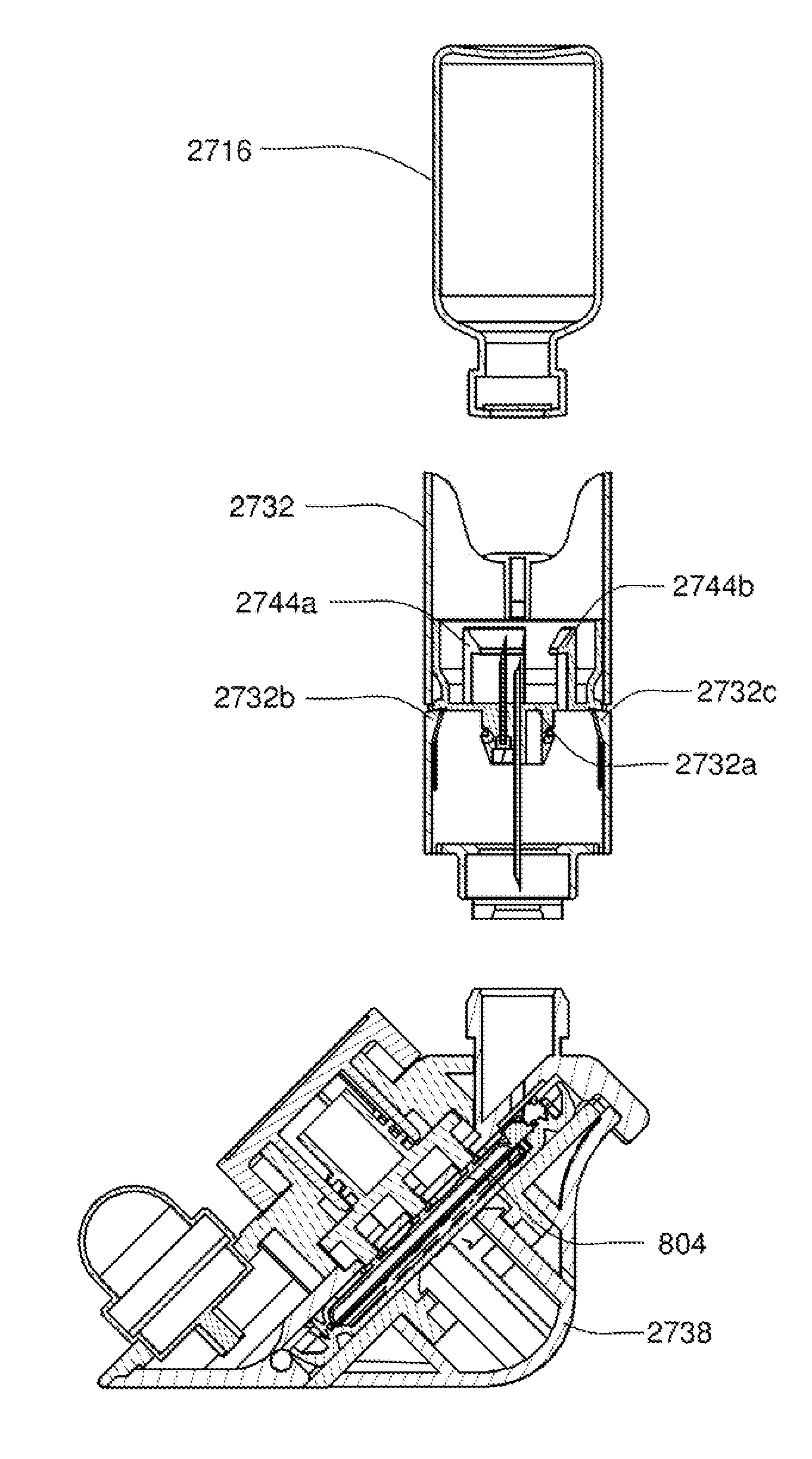
[0039]In accordance with one aspect of the present invention a fill adapter system for an infusion pump assembly is disclosed. The system includes a reusable fill adapter base, the base including a volume control mechanism to adjust an available fill volume of a reservoir of the infusion pump assembly and a pump mechanism configured to pump air into a fluid vial. The system also includes a vial adapter assembly including a first needle configured to penetrate a septum of the fluid vial for fluidly coupling the pump mechanism to the fluid vial and a second needle having a first e...

Problems solved by technology

Many potentially valuable medicines or compounds, including biologicals, are not orally active due to poor absorption, hepatic metabolism or other pharmacokinetic factors.
Additionally, some therapeutic compounds, although they can be orally absorbed, are sometimes required to be administered so often it is difficult for a patient to maintain the desired schedule.
These devices suffer from a number of drawbacks including the malfunction rate.
Reducing the size, weight and cost of these devices is also an ongoing challenge.
Additionally, these devices often apply to the skin and pose the challenge of frequent re-location for application.

Method used


Image

  • Apparatus, system and method for fluid delivery
  • Apparatus, system and method for fluid delivery
  • Apparatus, system and method for fluid delivery

Examples


Embodiment Construction

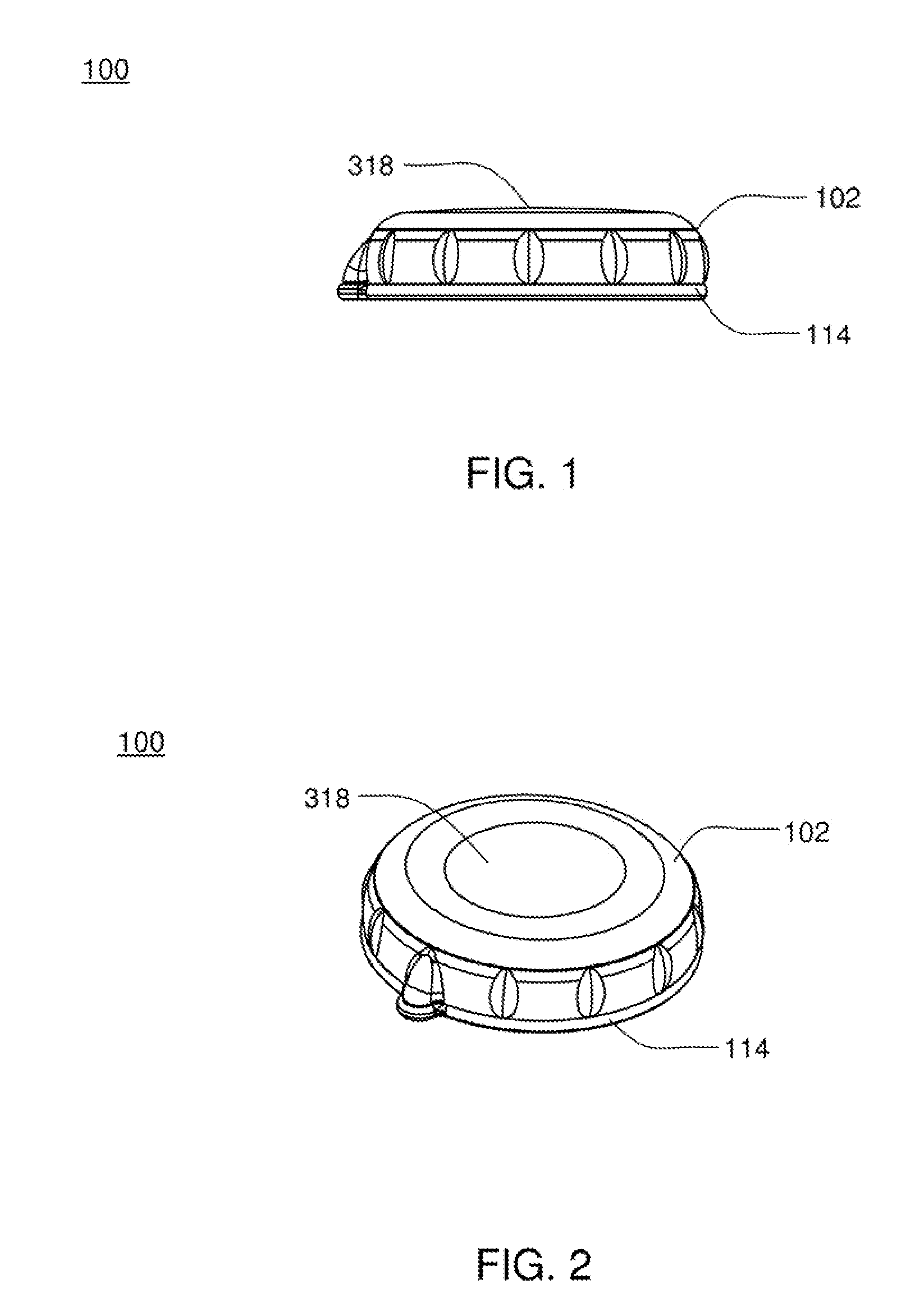
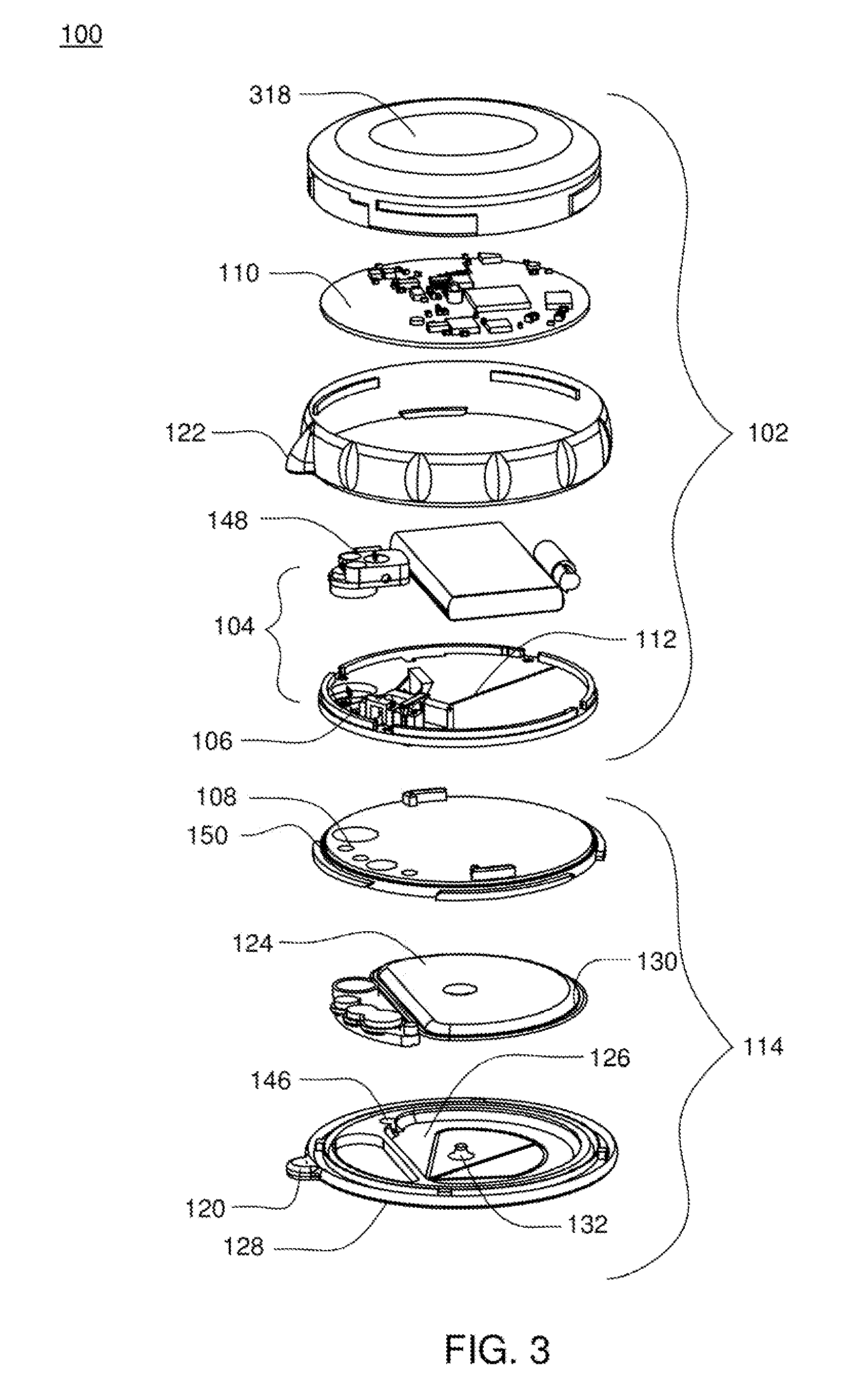
[0176]Referring to FIGS. 1-3, an infusion pump assembly 100 may include a reusable housing assembly 102. Reusable housing assembly 102 may be constructed from any suitable material, such as a hard or rigid plastic, that will resist compression. For example, use of durable materials and parts may improve quality and reduce costs by providing a reusable portion that lasts longer and is more durable, providing greater protection to components disposed therein.

[0177]Reusable housing assembly 102 may include mechanical control assembly 104 having a pump assembly 106 and at least one valve assembly 108. Reusable housing assembly 102 may also include electrical control assembly 110 configured to provide one or more control signals to mechanical control assembly 104 and effectuate the basal and / or bolus delivery of an infusible fluid to a user. Disposable housing assembly 114 may include valve assembly 108 which may be configured to control the flow of the infusible fluid through a fluid pa...


PUM

PropertyMeasurementUnit
Weightaaaaaaaaaa
Volumeaaaaaaaaaa
Hydrophobicityaaaaaaaaaa

Abstract

A fill adapter system for an infusion pump assembly. The system includes a reusable fill adapter base, the base including a volume control mechanism to adjust an available fill volume of a reservoir of the infusion pump assembly and a pump mechanism configured to pump air into a fluid vial. The system also includes a vial adapter assembly including a first needle configured to penetrate a septum of the fluid vial for fluidly coupling the pump mechanism to the fluid vial and a second needle having a first end configured to penetrate the septum of the fluid vial and a second end configured to penetrate a septum of the reservoir of the infusion pump assembly to allow transfer of fluid from the fluid vial to the reservoir of the infusion pump assembly in response to air being pumped into the fluid vial and a needle carriage adapted to carry the first needle and the second needle, wherein the needle carriage slidably attached to the interior of the vial adapter assembly, wherein the needle carriage adapted to slide from a vial end of the vial adapter to a receptacle end of the vial adapter.

Description

CROSS-REFERENCE TO RELATED APPLICATIONS[0001]The present application is a Non-Provisional patent application which claims priority from the following U.S. Provisional patent applications both of which are hereby incorporated herein by reference in its entirety:[0002]U.S. Provisional Patent Application Ser. No. 61 / 142,042, filed Dec. 31, 2008 and entitled Method, System and Apparatus for Verification of Volume and Pumping (Attorney Docket No. G78); and U.S. Provisional Patent Application Ser. No. 61 / 225,794, filed Jul. 15, 2009 and entitled Infusion Pump Assembly (Attorney Docket No. H48).[0003]The present application is also a Continuation-in-Part of U.S. patent application Ser. No. 12 / 347,985, filed Dec. 31, 2008, now U.S. Publication No. US-2009-0299277-A1, published Dec. 3, 2009 and entitled Infusion Pump Assembly (Attorney Docket No. G75), which is hereby incorporated herein by reference in its entirety, which application also claims priority from the following U.S. Provisional ...

Claims


Application Information

Patent Timeline
IPC IPC(8): A61J1/14A61J1/20B65B3/12
CPCA61J1/20H01Q9/265A61M5/142A61M5/14244A61M5/14248A61M5/16809A61M5/16886A61M2005/14268A61M2205/0266A61M2205/18A61M2205/3331A61M2205/3375A61M2205/3393A61M2205/3515A61M2205/3546A61M2205/3569A61M2205/3576A61M2205/50A61M2205/59A61M2205/6018A61M2205/70A61M2205/7536A61M2205/8237A61M2209/045A61M2209/086G01F11/086G05D7/0647G05D7/0676H01Q1/273A61M5/1413
Inventor LANIGAN, RICHARD J.FOO, BRIGHT CHONG KHUANGKAMEN, DEAN
Owner DEKA PROD LLP
Learn More