
Handle with Asymmetrical Configuration

a technology of symmetrical configuration and handle, which is applied in the direction of screwdrivers, multi-purpose tools, wrenches, etc., can solve the problems of symmetrical grip, hard to firmly hold the handle, and unsuitable for otherwise sized hands, and achieve the effect of convenient holding the handl

Active Publication Date: 2010-08-05
HSIEH CHIH CHING
View PDF5 Cites 11 Cited by
  • Summary
  • Abstract
  • Description
  • Claims
  • Application Information

AI Technical Summary

Benefits of technology

[0011]It is therefore a primary object of the present invention to provide a handle with asymmetrical configuration. The handle provides different holding ranges adapted to different sizes of hands, whereby different users can easily hold the handle to apply force thereto.
[0012]The handle of the present invention has a grip section and a neck section connected with a top end of the grip section. Multiple abutment regions are disposed on a circumference of the neck section for a user's thumb to press against the abutment regions. Multiple grip regions are disposed on a circumference of the grip section for the user's palm and other fingers to easily hold. The grip regions and the abutment regions are asymmetrically arranged, whereby different grip regions and different abutment regions of handle cooperate to provide many different holding ranges. Different users can choose their most suitable holding positions to hold the handle in accordance with the sizes of their hands. Accordingly, the users can more easily apply force onto the handle to operate the hand tool.

Problems solved by technology

However, the grip has fixed size and is suitable only for a certain size of hand.
To those users with larger hands or smaller hands, it is hard to firmly hold the grip.
Therefore, the symmetrical grip is only adapted to common-size hands, while being unsuitable for otherwise sized hands.
This is because in this case, the user's thumb will feel painful.
This is because in the case that a user presses his / her thumb against the front end of the handle, the user's thumb will feel painful.

Method used


Image

  • Handle with Asymmetrical Configuration
  • Handle with Asymmetrical Configuration
  • Handle with Asymmetrical Configuration

Examples


first embodiment

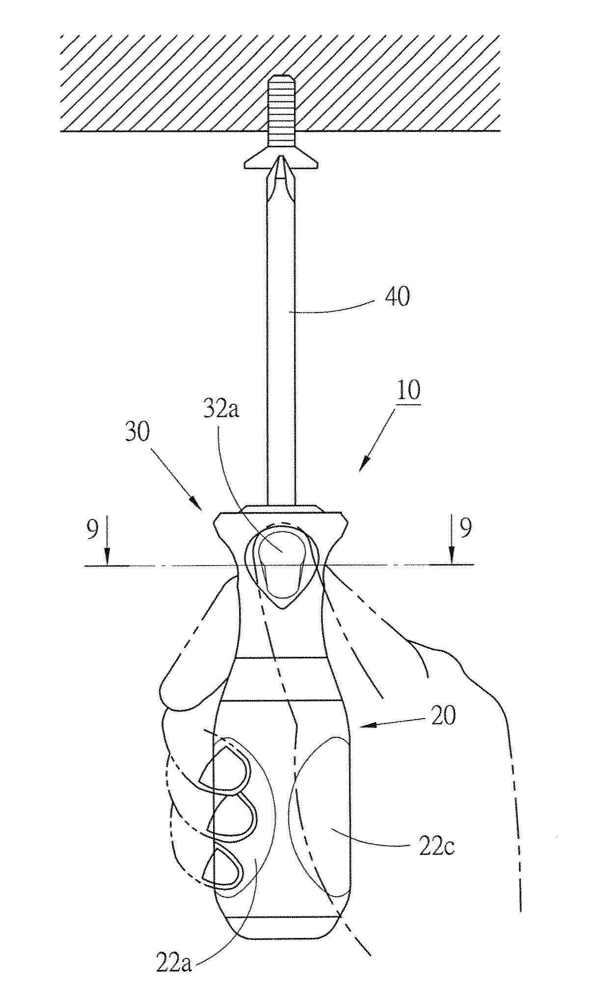
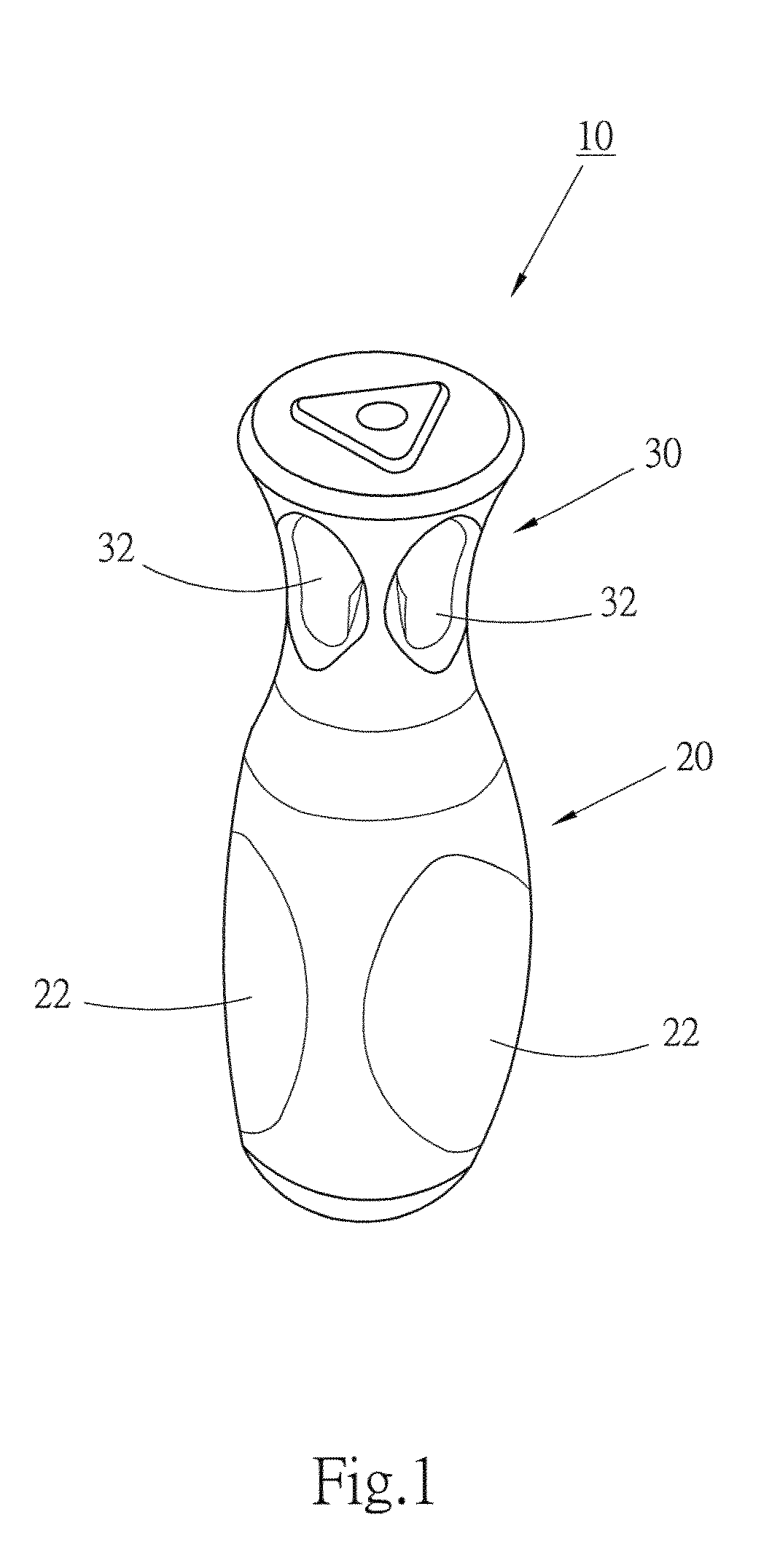
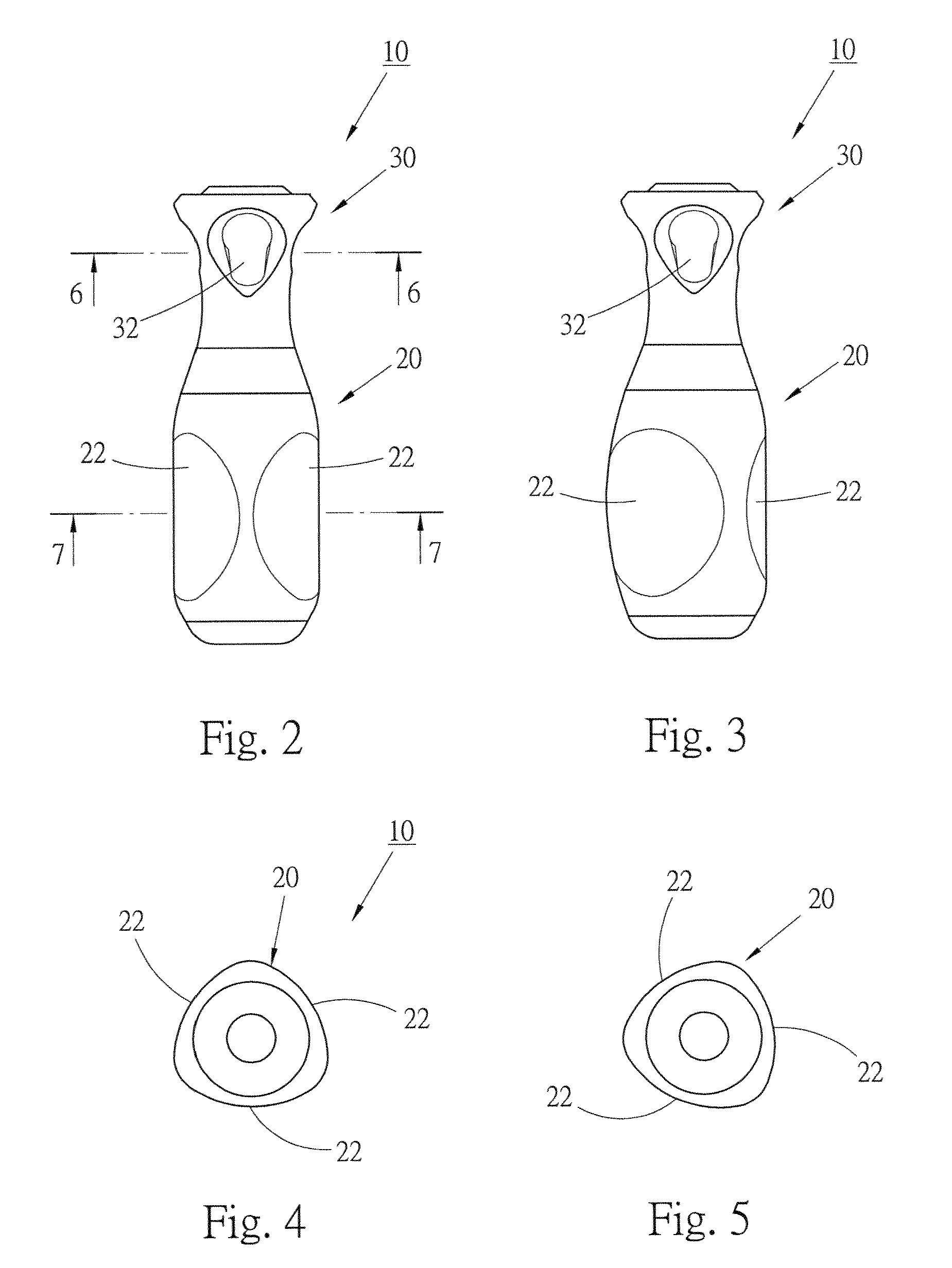
[0028]Please refer to FIGS. 1 to 3. the handle 10 of the present invention has a grip section 20 and a neck section 30 connected with a top end of the grip section 20 and generally formed with a smaller outer diameter. The handle 10 is applicable to a hand tool such as a screwdriver for a user to hold and exert force thereon.

[0029]Referring to FIGS. 4 and 5, an odd number of grip regions 22 is disposed on a circumference of the grip section 20 at equal intervals. For example, there are three or five grip regions 22. In this embodiment, the grip section has a substantially triangular cross-section to provide three grip regions 22 as shown in FIG. 7 for a user's palm to easily hold. The odd number of grip regions is adapted to the joints between the palm and fingers and meets human engineering requirements.

[0030]An even number of abutment regions 32 is disposed on a circumference of the neck section 30. Each abutment region 32 is, but not limited to, a recess. In this embodiment, the...

second embodiment

[0036]FIG. 14 is a sectional view of the handle 50 of the present invention, which is taken along the same line as FIG. 9.

[0037]The grip section 60 of the handle has a substantially quadrangular cross-section to provide four grip regions 62. The neck section 70 of the handle has a substantially triangular cross-section to provide three abutment regions 72. The grip regions 62 and the grip regions 72 are also asymmetrically arranged to form an asymmetrical configuration so as to provide many different holding ranges.

[0038]Moreover, in each abutment region 72 is disposed a material 74, which is different from and softer than the material of the handle. In this case, the abutment region has a smooth and flexible surface flush with the surface of the neck section. Similarly, a softer material can be disposed in each grip region 62 to provide flexible surface for easy holding.

third embodiment

[0039]FIG. 15 is a sectional view of the handle 80 of the present invention, in which the grip section 82 has a substantially pentagonal cross-section to provide five grip regions 84. The neck section 86 has a substantially quadrangular cross-section to provide four abutment regions 88. The abutment regions and the grip regions are also asymmetrically arranged to form an asymmetrical configuration. Soft materials can be also filled in the abutment regions and grip regions.

[0040]In this embodiment, holding ranges of an arc of 360 degrees, an arc of 288 degrees, an arc of 216 degrees, an arc of 306 degrees, an arc of 234 degrees, an arc of 324 degrees, an arc of 252 degrees, an arc of 342 degrees, an arc of 270 degrees and an arc of 198 degrees are provided.

[0041]Alternatively, the present invention can have an odd number of grip regions and an odd number of abutment regions in asymmetrical relationship with each other. As shown in FIG. 16, the grip section 92 of the handle 90 has fiv...


PUM


Abstract

The invention provides a handle of a hand tool. The handle has a grip section and a neck section. Multiple abutment regions are disposed on a circumference of the neck section for a user's thumb to press against the abutment regions. Multiple grip regions are disposed on a circumference of the grip section for the user's palm and other fingers to hold. The grip regions and the abutment regions are asymmetrically arranged, whereby different grip regions and different abutment regions of handle cooperate to provide many different holding ranges. Different users can choose their most suitable holding positions to hold the handle in accordance with the sizes of their hands.

Description

[0001]This application is a Continuation-in-Part of application Ser. No. 11 / 389,191, entitled HANDLE FOR HAND TOOL, filed on Mar. 27, 2006.FIELD OF THE INVENTION[0002]The present invention is related to a handle of a hand tool, and more particularly to a handle of a screwdriver, which provides different holding ranges for different users to easily hold the handle.BACKGROUND OF THE INVENTION[0003]The handle of a hand tool such as a screwdriver is for a user to hold and exert force onto the hand tool. Accordingly, the configuration of the handle determines the holding effect and force application effect of a user when operating the hand tool.[0004]Different users have different sizes of palms and different lengths of fingers. The conventional handle is generally designed without taking into consideration that different users have different sizes of hands.[0005]The conventional handle generally has a symmetrical configuration. U.S. Pat. No. 3,173,462 discloses a grip 12 of a screwdrive...

Claims


Application Information

Patent Timeline
IPC IPC(8): B25B23/16
CPCB25G1/102B25G1/105Y10T16/48Y10T16/498Y10T16/476Y10S16/12
Inventor HSIEH, CHIH-CHING
Owner HSIEH CHIH CHING
Learn More