
Multi-event telescopic platform

Inactive Publication Date: 2010-08-05
IRWIN SEATING
View PDF8 Cites 11 Cited by
  • Summary
  • Abstract
  • Description
  • Claims
  • Application Information

AI Technical Summary

Benefits of technology

[0008]The lead screws may extend from opposing sides of the same gear box, with the gear box configured to rotate the differently handed lead screws. Activation of the single gear box thereby causes both swing arms to move toward the vertical position. In another embodiment, only a first one of the lead screws is connected to the gear box, with the other lead screw connected to the first lead screw. In this embodiment, the swing arms may be long enough to extend beyond the mid-point of the platform to overlap each other when in the canted position. The longer swing arms may increase the height of the platform in the raised position. In yet another embodiment, each lead screw may be connected to a separate gear box.
[0009]The benefits of the proposed system are based on simplistic design, light weight construction and simplicity associated with operating. In the present invention, structural and live loading is supported by the swing arms when the platform is in the raised position. As a result, the loads need not be supported by the lift mechanism like they are in a vertical lifting lead screw or a scissor lift system. The telescoping verticals support members may be used for alignment purposes only, and are not required for load bearing when the platform system is in the raised position. In addition, the present system enables individual platforms to be independently raised and lowered, and only a low torque rotational tool, such as a handheld drill, is required to operate the gear box.

Problems solved by technology

The scissor lift provides lift while minimizing the initial height of the system; however, it suffers from a number of drawbacks.
In addition, it is a complicated system and therefore tends to be costly.
Similar drawbacks exist for vertical hydraulic and pneumatic lead screw lift systems, and for other lift systems, in that they provide direct vertical lift to the platform which requires them to support the lift system and live loads.
Without an additional locking mechanism, the platforms supported by these lift mechanisms may collapse upon a failure of the lift mechanism.

Method used


Image

  • Multi-event telescopic platform
  • Multi-event telescopic platform
  • Multi-event telescopic platform

Examples


Embodiment Construction

I. Overview

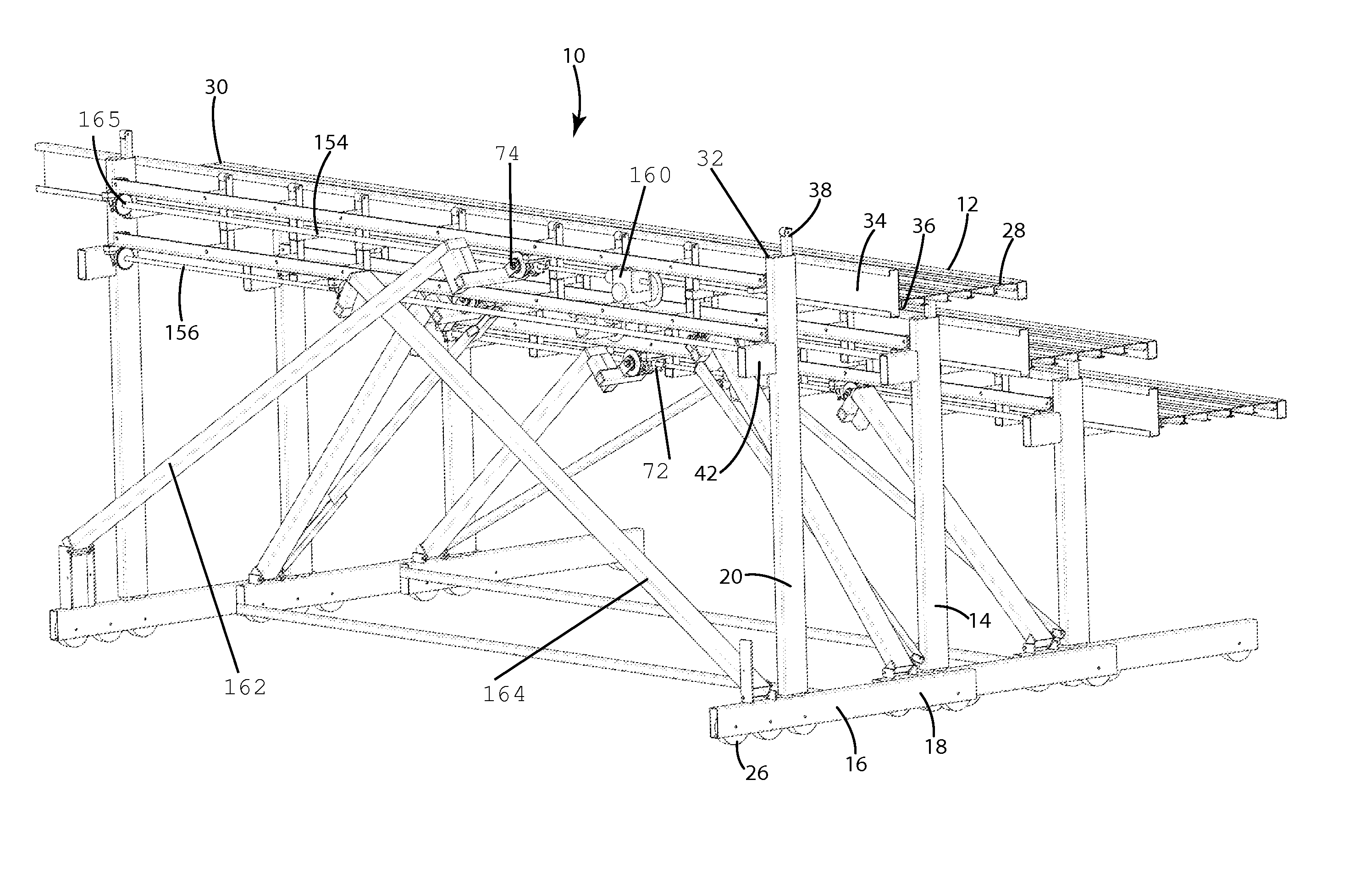
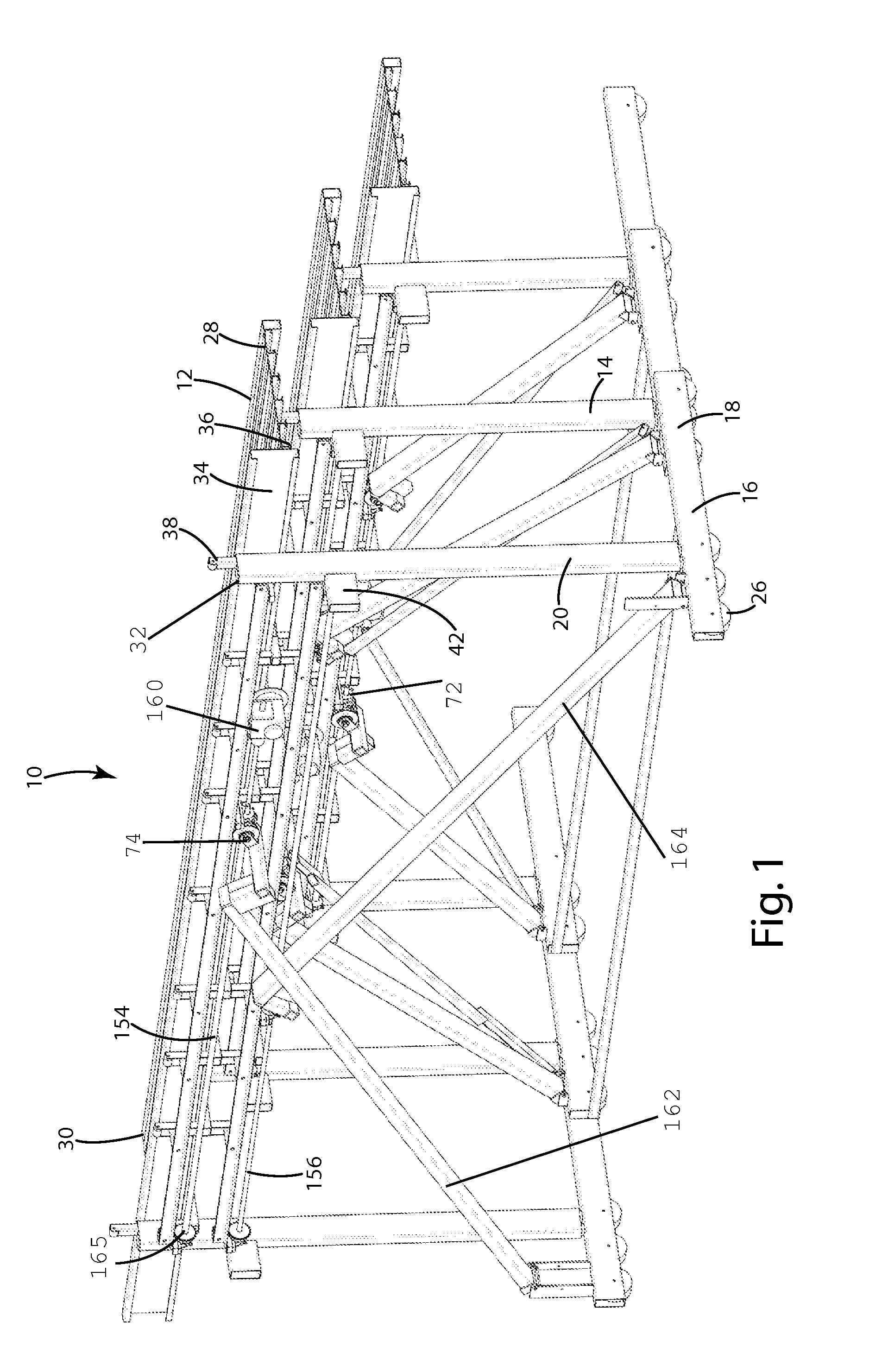
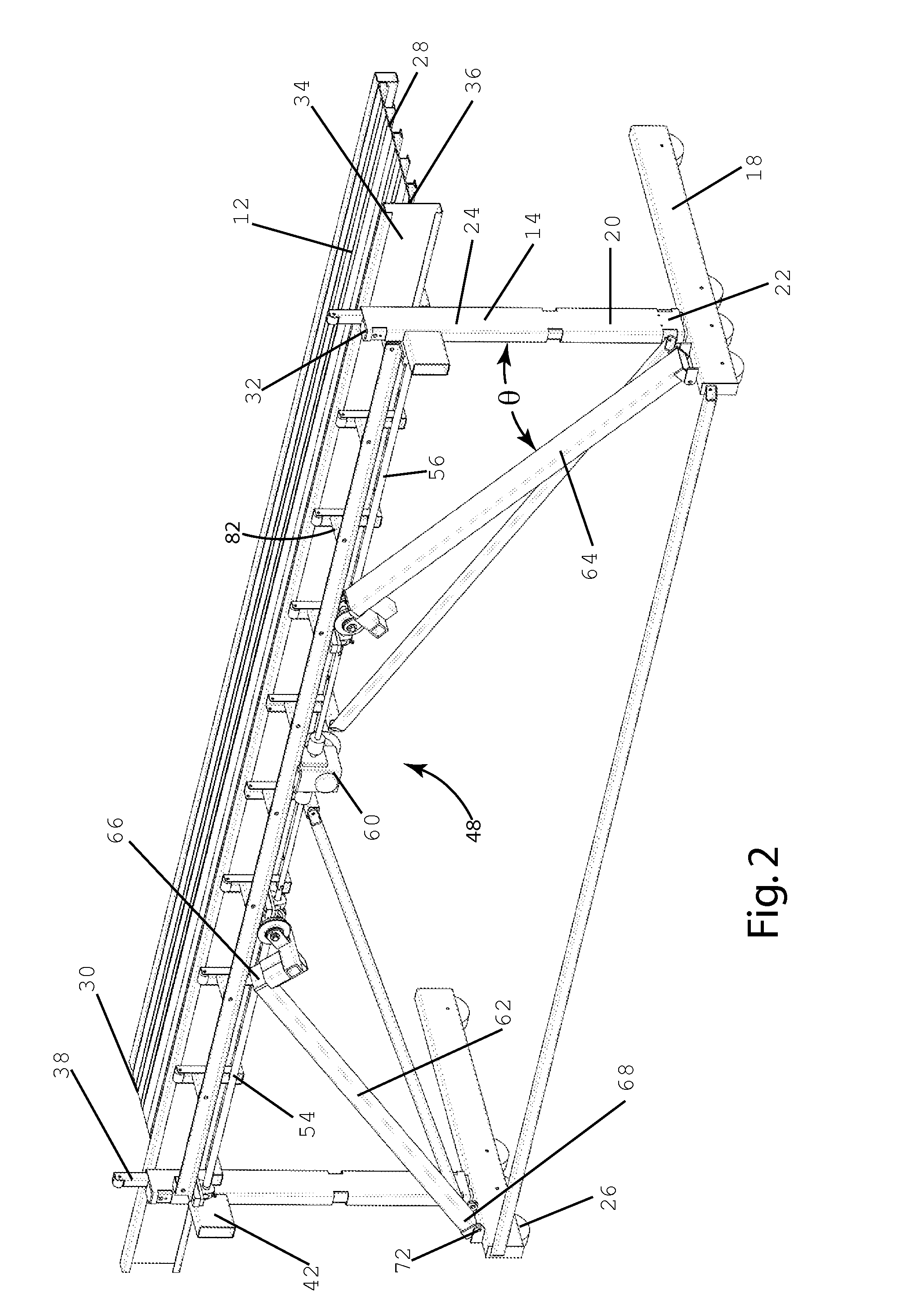
[0015]A variable rise platform seating system according to one embodiment of the present invention is shown in FIG. 1 and generally designated 10. In general, the described embodiment uses a swing arm mechanism to lift the deck surface of a telescopic platform. As shown in FIG. 1, each platform seating system 10 includes a generally horizontal platform deck 12 attached to a support structure 14. The support structure 14 may be movable, such that multiple platform systems 10 can be moved between an extended position (shown in FIG. 1) and a retracted position (not shown) in which the platform decks 12 and their support structures 14 are nested with each other. Each platform system 10 is capable of vertical movement between a lowered position, shown in FIG. 2, and a raised position, shown in FIG. 2a. The platform system 10 is moved between the raised and lowered positions by movement of swing arms between a canted position and a vertical position.

II. Structure

[0016]The suppo...


PUM


Abstract

A platform system includes swing arms for moving the platform from a lowered position to a raised position. In one embodiment, a pair of swing arms and a pair of telescoping vertical members are mounted to opposing frame members. The swing arms are capable of moving from a canted position to a vertical position, which extends the telescoping vertical members and raises the platform to the raised position. The swing arms are connected to a drive mechanism that moves the swing arms from the canted position to the vertical position. The drive mechanism may include a gear box, and a pair of lead screws connected to the gear box. The lead screws may extend from opposing sides of the same gear box, with the gear box configured to rotate the differently handed lead screws.

Description

BACKGROUND OF THE INVENTION[0001]The present invention relates to platform seating assemblies, and more particularly to a system for raising, lowering, and storing one or more components of a platform seating assembly.[0002]Platform seating assemblies are well known for providing seating accommodations for multiple people, often in large capacities such as at sporting events. These systems typically include a platform that provides a seating surface, and a base support structure that supports the platform at a desired height. In some cases, the platform is configured for users to sit directly on the upper surface—commonly known as bleachers—whereas in other cases, the platform is configured to receive individual seats attached to the upper surface of the platform. In many applications multiple platforms are provided at increasing heights to increase the number of seats at a particular venue and to provide each platform with an unobstructed forward view. The support structures of eac...

Claims


Application Information

Patent Timeline
IPC IPC(8): E04H3/12
CPCE04H3/123
Inventor WISNER, DONALD W.SOUTHWELL, DAVID R.HEATHERINGTON, DAVID W.VAN DE VEN, MICHIEL P.RUPAR, DENNIS V.PLUMERT, TERRY L.WALWOOD, JOHN W.
Owner IRWIN SEATING
Learn More