
Electric scissors

a technology of electric scissors and blades, applied in the field of electric scissors, can solve the problems of large torque required as the blades are closed, deformation of the durability of the drive system, and application to the drive system, and achieve the effects of large cutting torque, large cutting torque, and increased cutting for

Inactive Publication Date: 2010-08-05
MAX CO LTD
View PDF24 Cites 20 Cited by
  • Summary
  • Abstract
  • Description
  • Claims
  • Application Information

AI Technical Summary

Benefits of technology

[0014]One or more embodiments of the invention provide electric scissors capable of obtaining a torque required for cutting an object to be cut without increasing a weight thereof.
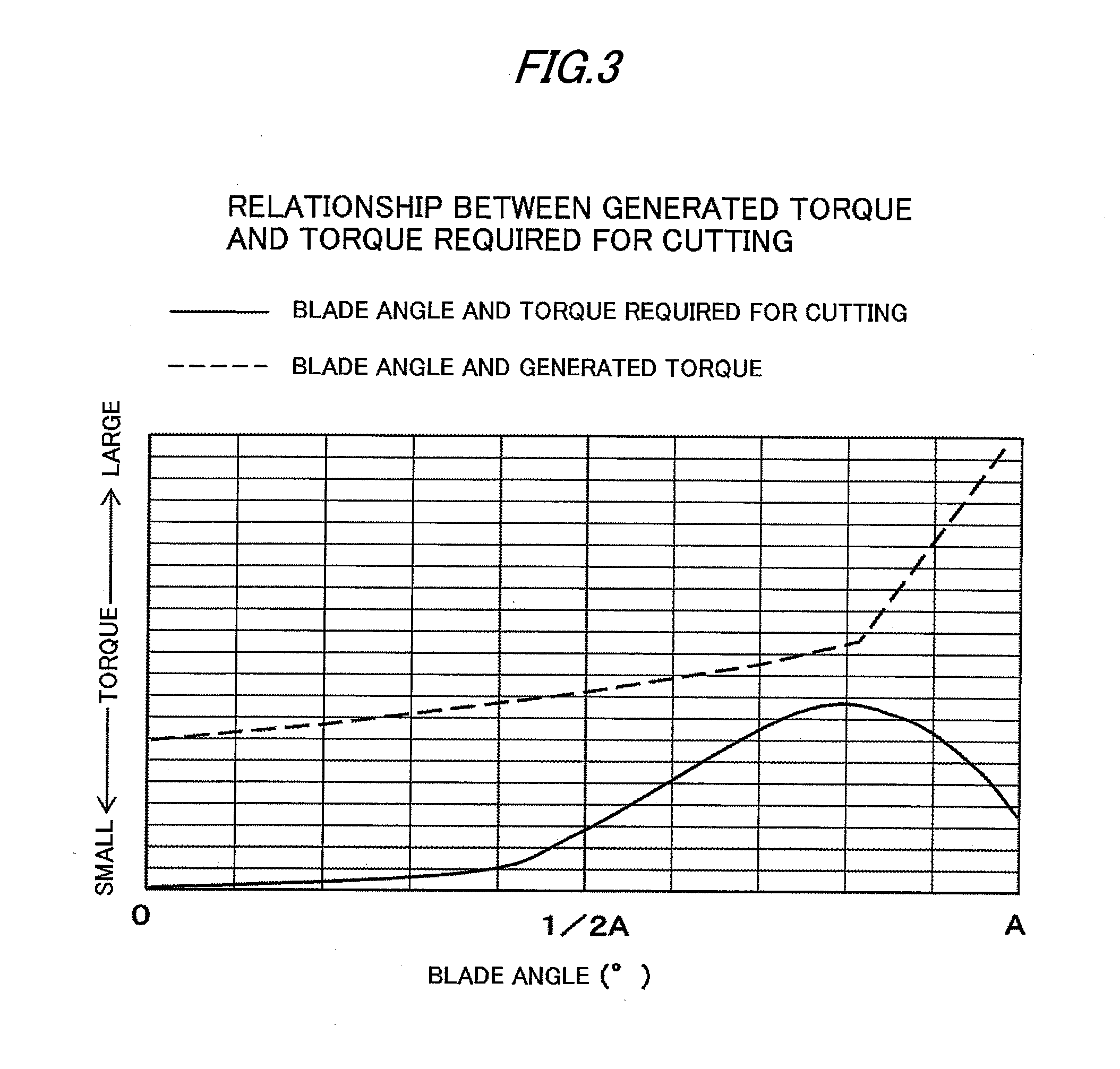
[0017]According to the electric scissors having the above structure, since a large cutting torque can be generated in the latter half of the closing operation of the blades requiring a large torque to cut an object to be cut, such as a branch, the torque required to cut the object to be cut can be obtained without increasing the weight of the mechanisms of the electric scissors.
[0018]Hence, a load applied to the drive system of the electric scissors can be reduced, and the drive system can be made compact in size and light in weight without degrading durability. Since the drive system can be made compact in size and light in weight, the entire apparatus can also be made compact in size and light in weight. Consequently, the operability of the tool that is held in the hand and used can be improved.

Problems solved by technology

However, a large torque is required as the blades are closed.
Hence, a load applied to the drive system, such as the ball screw mechanism, becomes large, and the durability of the drive system is degraded.
Consequently, although the electric scissors are used as a tool held in the hand, it is difficult to make the electric scissors light in weight, and the apparatus eventually becomes large in size and the operability thereof is degraded.
It is thus difficult to make the electric scissors light in weight, and the apparatus eventually becomes large in size.
On the other hand, if the gears are decreased in thickness to make the apparatus compact in size and light in weight, the durability thereof is degraded.

Method used


Image

  • Electric scissors
  • Electric scissors
  • Electric scissors

Examples


first exemplary embodiment

A Configuration Example of Electric Scissors

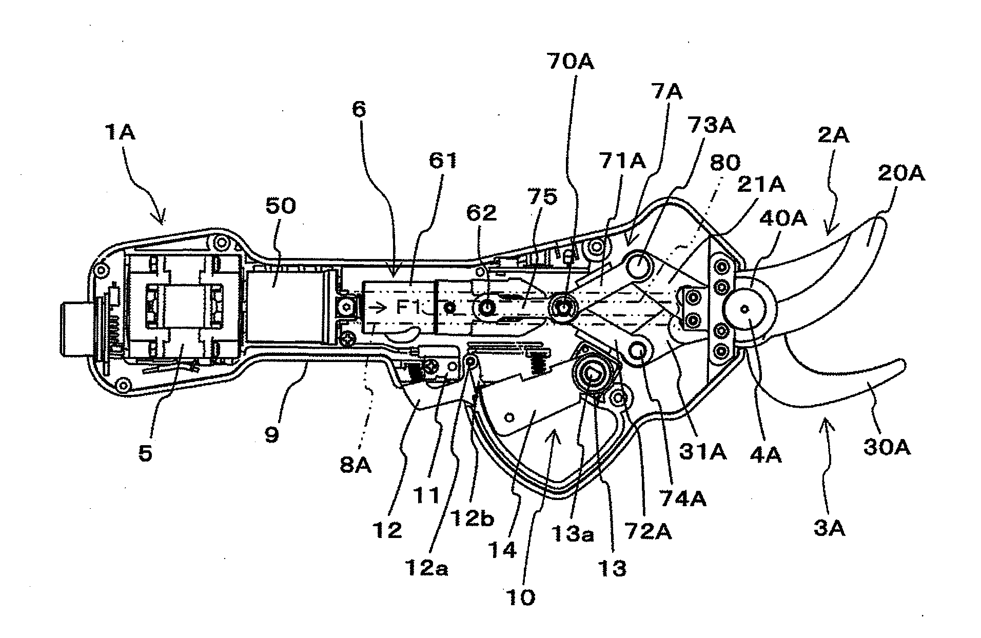
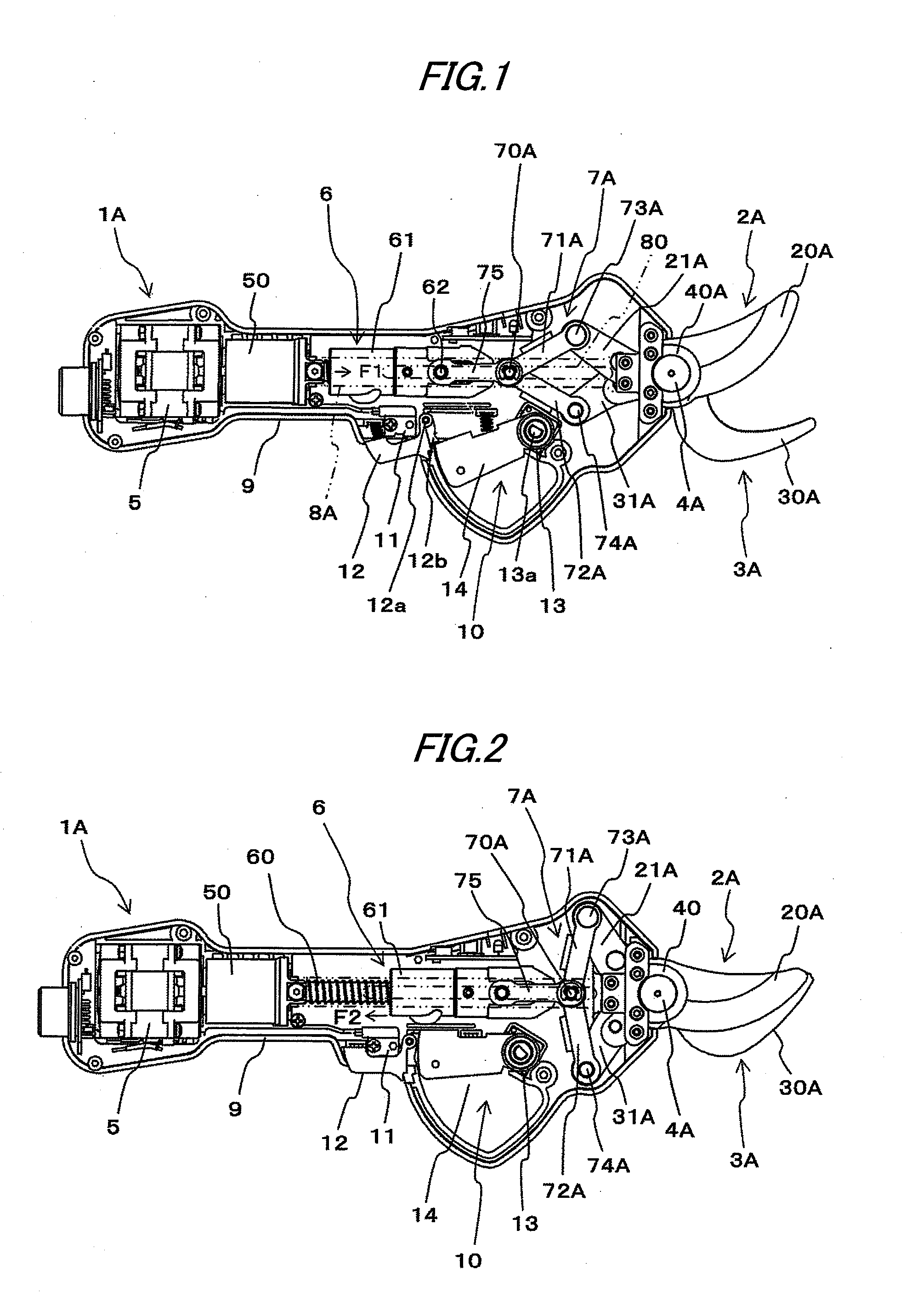
[0029]FIGS. 1 and 2 are side sectional views showing a configuration example of electric scissors according to a first exemplary embodiment. FIG. 1 shows a state in which the blades thereof are opened, and FIG. 2 shows a state in which the blades are closed.

[0030]In electric scissors 1A according to the first exemplary embodiment, a first movable blade 2A and a second movable blade 3A are rotatably supported by a shaft 4A serving as a fulcrum.

[0031]In the electric scissors 1A, the rotation of a motor 5 is converted into a linear motion using a ball screw mechanism 6, and the drive power of the motor 5, the rotation of which is converted into a linear motion, is transmitted to the first movable blade 2A and the second movable blade 3A using a toggle link mechanism 7A. As a result, the first movable blade 2A and the second movable blade 3A are rotated around the shaft 4A serving as a fulcrum, thereby being opened / closed.

[0032]In the electric...

second exemplary embodiment

A Configuration Example of Electric Scissors

[0071]FIGS. 4 and 5 are side sectional views showing a configuration example of electric scissors according to a second exemplary embodiment; FIG. 4 shows a state in which the blades thereof are opened, and FIG. 5 shows a state in which the blades are closed. In FIGS. 4 and 5, mechanisms for driving one of the blades of the electric scissors are shown, and the housing, the operation section, etc. thereof are not shown.

[0072]Electric scissors 1B according to the second exemplary embodiment have a movable blade 2B and a fixed blade 3B, and the movable blade 2B is rotatably supported by a shaft 4B serving as a fulcrum.

[0073]In the electric scissors 1B, the rotation of a motor 5 is converted into a linear motion using a ball screw mechanism 6, and the drive power of the motor 5, the rotation of which is converted into a linear motion, is transmitted to the movable blade 2B using a toggle link mechanism 7B. As a result, the movable blade 2B is ...


PUM


Abstract

Electric scissors (1A, 1B) is provided with: a first blade (2A, 2B); a second blade (3A, 3B); a toggle link mechanism (7A, 7B) including a first link (71A, 71B), a second link (72A, 72B), and a drive shaft (70A, 70B); and a drive section (5, 6). One end of the first link (71A, 71B) is rotatably connected to a transmission portion (21A, 21B) of the first blade (2A, 2B). One end of the second link (72A, 72B) is rotatably connected to a transmission portion (31A, 31B) of the second blade (3A, 3B). The other end of the first link (71A, 71B) is rotatably connected to the other end of the second link (72A, 72B) through the drive shaft (70A, 70B). The drive section (5, 6) is configured to open / close the first blade (2A, 2B) and the second blade (3A, 3B) by displacing the drive shaft (70A, 70B) in a direction perpendicular to an axial direction of the drive shaft (70A, 70B).

Description

BACKGROUND OF THE INVENTION[0001]1. Field of the Invention[0002]The present invention relates to electric scissors, used to prune branches of trees or the like, for cutting objects to be cut, such as the branches, by opening and closing the blades using a drive power of a motor.[0003]2. Background Art[0004]Conventionally, branches or the like have been pruned with scissors by opening / closing blades of scissors with a hand of the user. However, for the purpose of saving labor of this work, electric scissors are proposed that can cut objects to be cut, such as the branches, by opening / closing the blades using a drive power of a motor.[0005]Such electric scissors include a fixed blade and a movable blade being rotatable around a shaft serving as a fulcrum. A configuration referred to as a link type and a configuration referred to as a gear type are known as the configurations of systems for driving the movable blade.[0006]Link-type electric scissors are configured so that the movable b...

Claims


Application Information

Patent Timeline
IPC IPC(8): A01G3/037B26B15/00B26B13/26
CPCA01G3/037A01G3/08B26B15/00
Inventor ISHIGURO, HIROKI
Owner MAX CO LTD
Learn More