
Spacer block with sensor for total knee arthroplasty

a technology of a spacer block and a sensor, which is applied in the field of spacer block with a sensor for total knee arthroplasty, can solve the problems of reduced knee range of motion for patients, post-operative pain, and inability to support the knee joint,

Inactive Publication Date: 2010-07-29
UNIV OF FLORIDA RES FOUNDATION INC
View PDF4 Cites 15 Cited by
  • Summary
  • Abstract
  • Description
  • Claims
  • Application Information

AI Technical Summary

Benefits of technology

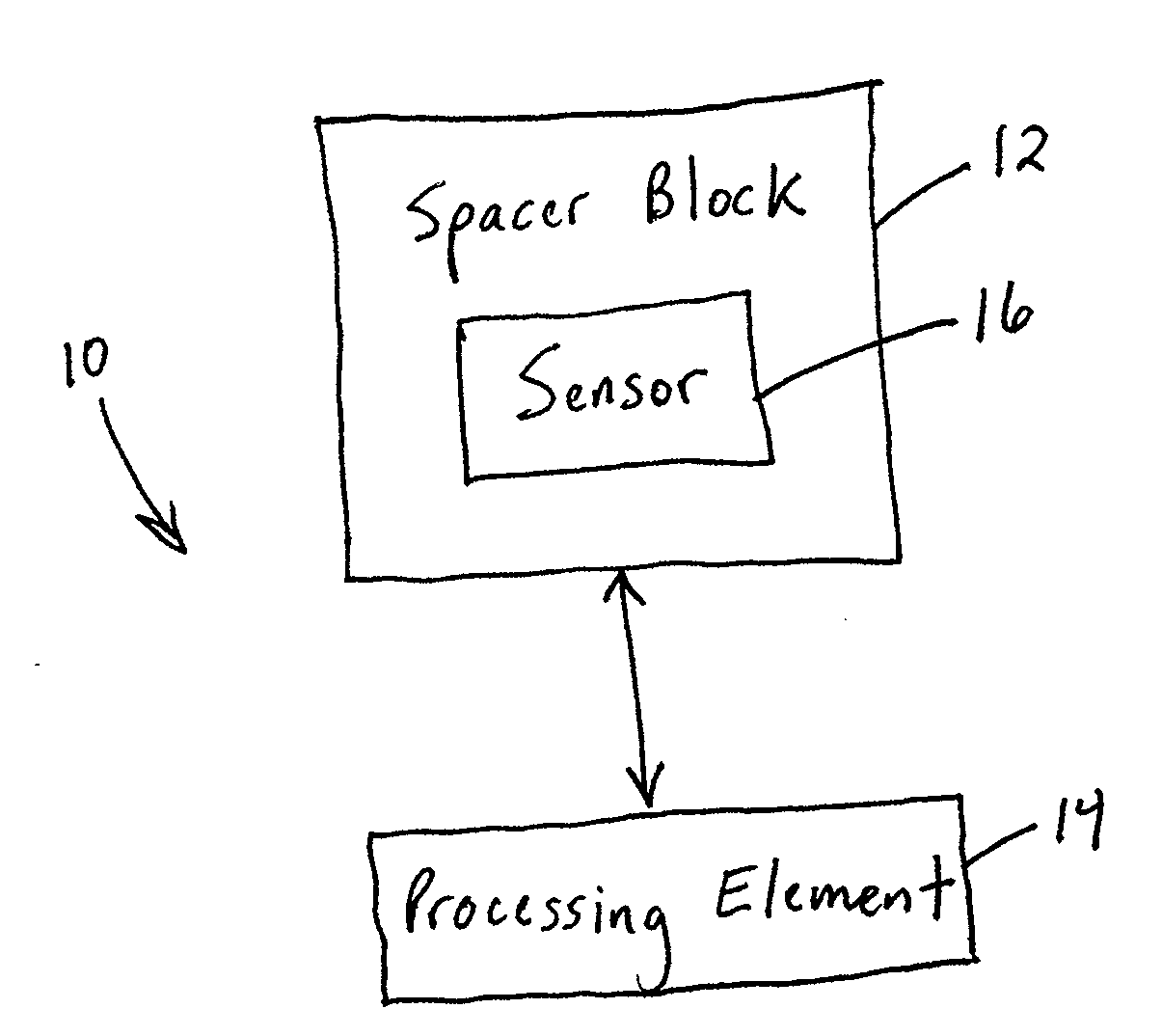
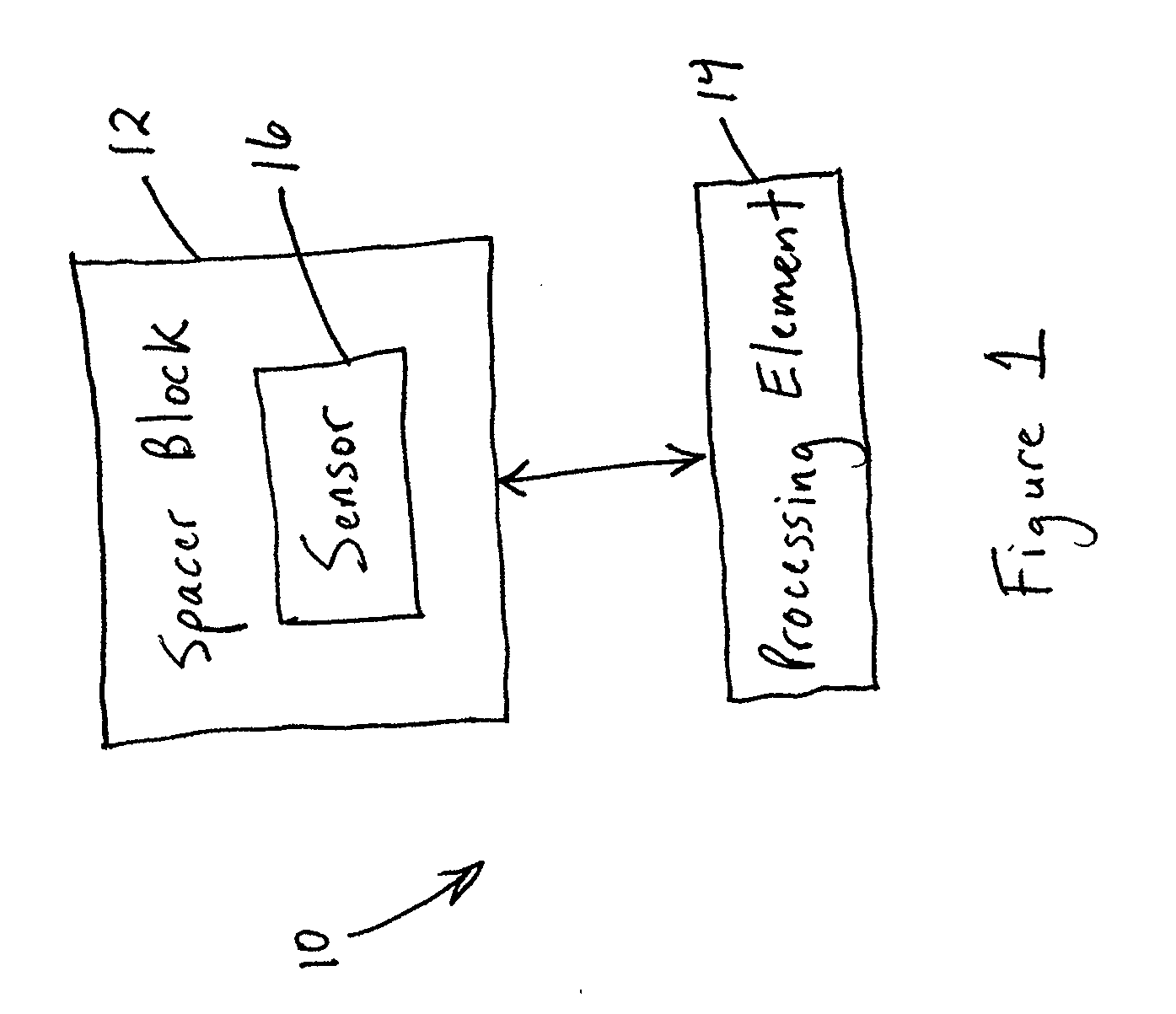
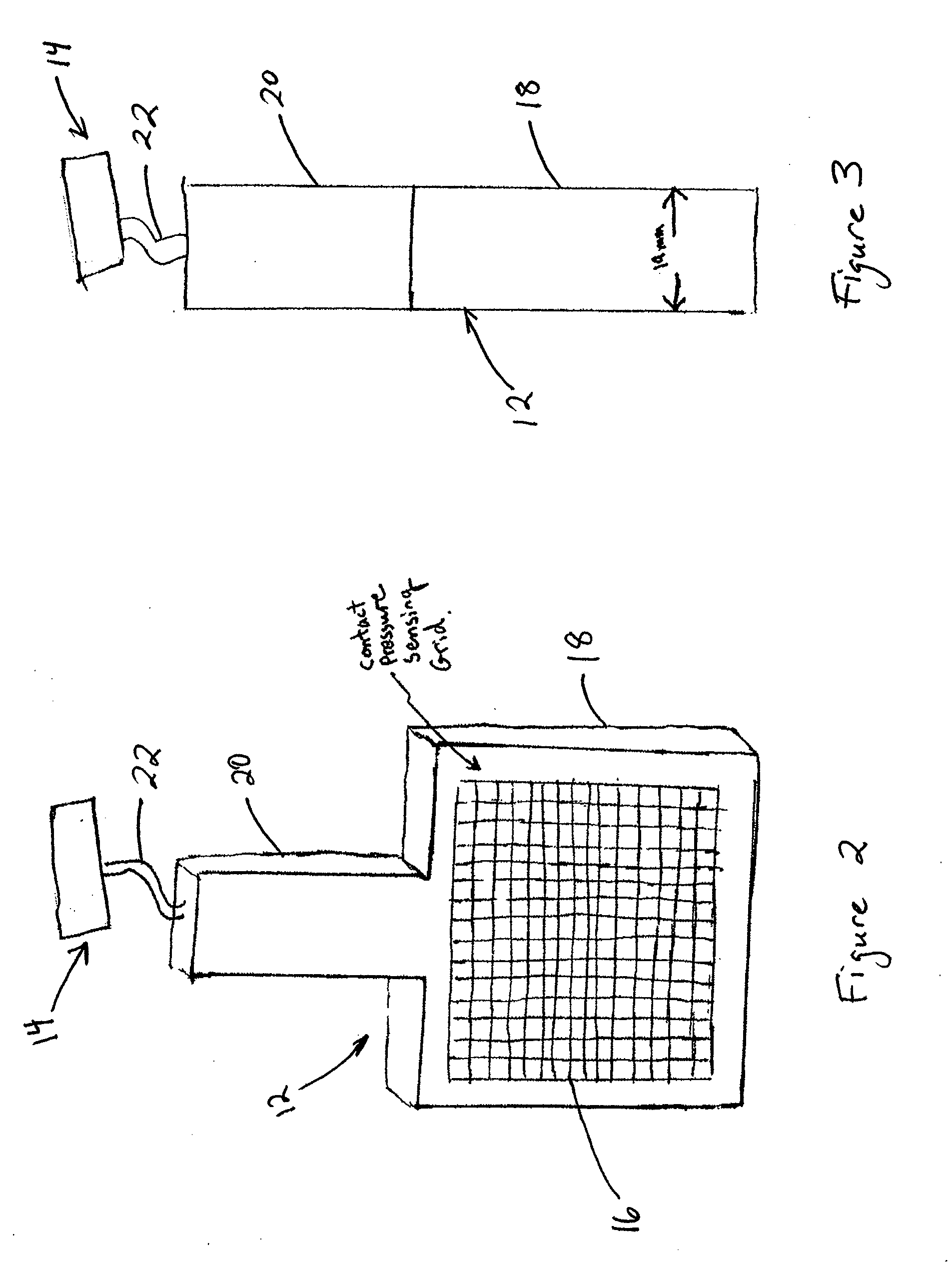
The present invention relates to a force sensing system for assisting a surgeon during total knee arthroplasty. The system includes a spacer block that receives forces from the resected femur and tibia, a sensor array that measures the forces, and a processing element that generates information about the forces. The system also includes a display that shows the information about the forces on the spacer block, which can display a two-dimensional image of the contact pressure and an indication of an anisotropic contact pressure. The sensor array may be integrated with the spacer block. The technical effect of the invention is to provide a system that can help the surgeon better understand the forces applied during the procedure and improve the accuracy of the surgery.

Problems solved by technology

If not enough bone material is excised then an “overstuffing” situation occurs which stretches the collateral ligaments leading to post-operative pain, stiffness, and reduced knee range of motion for the patient.
If too much bone material is excised, then “under-stuffing” will occur leading to looseness of the collateral ligaments resulting in lack of support in the knee joint and possibly future risk of injury.
Another source of post-operative pain and reduced range of motion is the accidental creation of “up-sloping” or “down-sloping” on the femoral or tibial resection plane.
Slight sloping of the resection plane can lead to reduced flexion or extension space and therefore limited flexion or extension after surgery.
However, due to differences in joint structure between the individuals and large amount of “play” or wiggle room the joint has when surgeons are artificially flexing and extending the joints to test during the procedure, there are still occurrences of the above-described negative conditions.

Method used


Image

  • Spacer block with sensor for total knee arthroplasty
  • Spacer block with sensor for total knee arthroplasty
  • Spacer block with sensor for total knee arthroplasty

Examples


Embodiment Construction

[0012]The present invention will now be described more fully hereinafter with reference to the accompanying drawings, in which various embodiments of the invention are shown. This invention may, however, be embodied in many different forms and should not be construed as limited to the embodiments set forth herein. Rather, these embodiments are provided so that this disclosure will be thorough and complete, and will fully convey the scope of the invention to those skilled in the art. Like numbers refer to like elements throughout.

Overview

[0013]Various embodiments of the present invention are configured to assist a surgeon during total knee arthroplasty (“TKA”). In particular, certain embodiments of the present invention address the problem associated with post-TKA collateral ligament tightness or looseness, and / or reduced flexion or extension of the knee joint. According to one embodiment of the present invention, a spacer block is provided that includes one or more sensors, and that...


PUM


Abstract

Embodiments of the present invention relate to a force sensing system and method for total knee arthroplasty. For example, a force sensing system includes a spacer block that is adapted to be positioned adjacent a resected distal femur and a resected proximal tibia. The spacer block is configured to receive a first force applied by the resected distal femur and a second force applied by the resected proximal tibia. The force sensing system also includes at least one sensor that is associated with the spacer block and that is adapted to measure one or more forces exerted on the spacer block. Moreover, the force sensing system includes a display that is adapted for displaying an indication of the one or more forces measured by the at least one sensor.

Description

CROSS REFERENCE TO RELATED APPLICATION[0001]The present application claims priority from U.S. Provisional Application No. 60 / 790,139 filed Apr. 7, 2006, the contents of which are incorporated herein by reference.BACKGROUND[0002]During total knee arthroplasty, portions of the distal femur and proximal tibia are excised to be replaced by the knee implant. The dimensions of the excised regions should typically match the dimensions of the knee joint replacement so as to not alter the stress on the collateral ligaments that hold the joint together. If not enough bone material is excised then an “overstuffing” situation occurs which stretches the collateral ligaments leading to post-operative pain, stiffness, and reduced knee range of motion for the patient. If too much bone material is excised, then “under-stuffing” will occur leading to looseness of the collateral ligaments resulting in lack of support in the knee joint and possibly future risk of injury. Another source of post-operativ...

Claims


Application Information

Patent Timeline
Patent Type & Authority Applications(United States)
IPC IPC(8): A61B5/00A61B17/58
CPCA61B5/103A61B5/4528A61B5/4533A61B19/46A61B5/6878A61F2/38A61F2/4657A61F2/4684A61F2002/4666A61B2019/465A61B90/06A61B2090/065
Inventor BEWERNITZ, MARK ALANGEAREN, PETER F.
Owner UNIV OF FLORIDA RES FOUNDATION INC
Learn More