
Apparatus suitable for transporting client signals, and apparatus and method suitable for mapping or demapping tributary slots for transport of client signals

a client signal and apparatus technology, applied in the field of technology suitable for transporting client signals, can solve the problems of ethernet signal bit-transparent mapping limitations, 10 gbe signal cannot be bit-transparently mapped into otu, etc., and achieve the effect of increasing data capacity

Inactive Publication Date: 2010-07-22
ELECTRONICS & TELECOMM RES INST
View PDF9 Cites 28 Cited by
  • Summary
  • Abstract
  • Description
  • Claims
  • Application Information

AI Technical Summary

Benefits of technology

The patent describes a technology that can adjust the bandwidths of client signals while bit-transparently receiving and multiplexing the signals over an optical transport network. This is achieved by a client signal transporting apparatus that includes a tributary slot allocation unit and an optical multiplexing unit. The technology allows for the allocation of a portion of the payload area of an optical transport signal equally in units of predetermined tributary slots and the remainder of the payload area in units of predetermined extra tributary slots or fixed stuff bytes. The client signal is then mapped into the allocated payload area using the allocated tributary slots and the allocated extra tributary slots or fixed stuff bytes. The technology also allows for the adjustment of the bandwidth by extending the mapping region to increase the data capacity in which tributary slots can be allocated. Overall, the technology provides a flexible and efficient way to transport client signals over optical networks.

Problems solved by technology

However, since a payload capacity of OTU2 is about 99.952 Gbit / s and the capacity of 10 GbE is 10.3125 Gbit / s, a 10 GbE signal cannot be bit-transparently mapped into OTU2.
In other words, since the conventional optical transport signals are defined based on the SDH, there are limitations in bit-transparently mapping Ethernet signals.

Method used


Image

  • Apparatus suitable for transporting client signals, and apparatus and method suitable for mapping or demapping tributary slots for transport of client signals
  • Apparatus suitable for transporting client signals, and apparatus and method suitable for mapping or demapping tributary slots for transport of client signals
  • Apparatus suitable for transporting client signals, and apparatus and method suitable for mapping or demapping tributary slots for transport of client signals

Examples


Embodiment Construction

[0038]The detailed description is provided to assist the reader in gaining a comprehensive understanding of the methods, apparatuses and / or systems described herein. Various changes, modifications, and equivalents of the systems, apparatuses, and / or methods described herein will likely suggest themselves to those of ordinary skill in the art. Also, descriptions of well-known functions and constructions are omitted to increase clarity and conciseness.

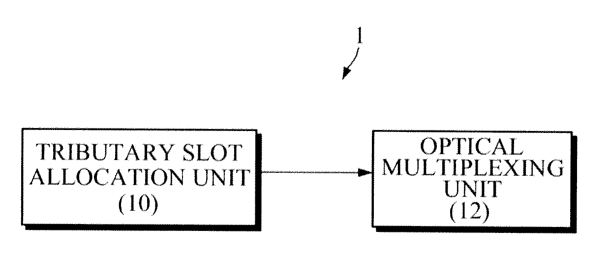
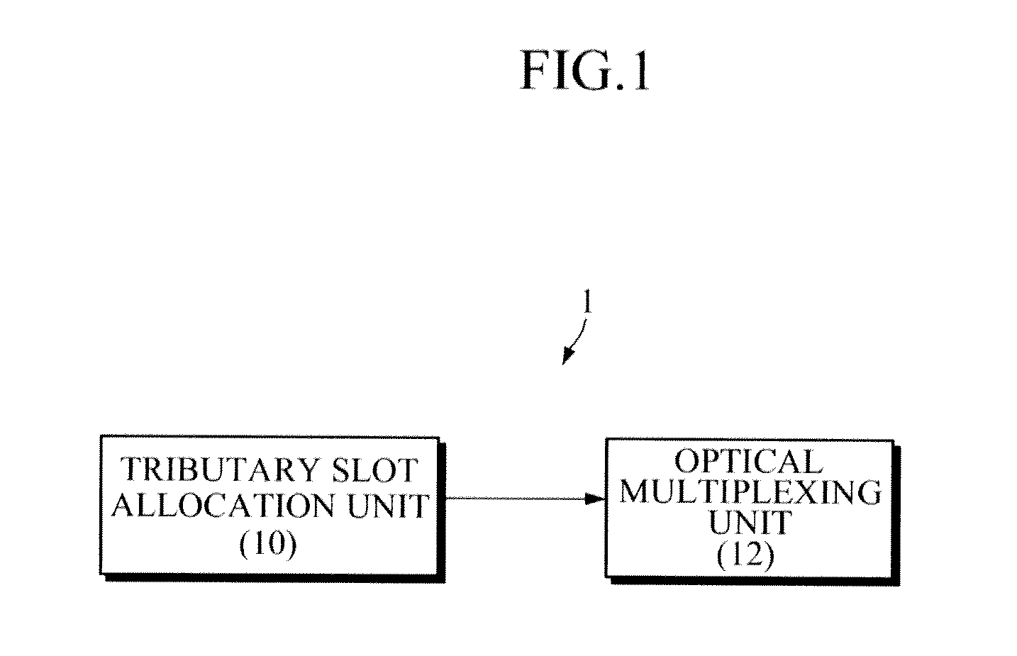
[0039]FIG. 1 illustrates a configuration of a client signal transporting apparatus 1 according to an exemplary embodiment.

[0040]Referring to FIG. 1, the client signal transporting apparatus 1 includes a tributary slot allocation unit 10 and an optical multiplexing unit 12. The client signal transporting apparatus 1 transports client signals using the Optical Transport Hierarchy (OTH) over an Optical Transport Network (OTN). The client signals include packet signals such as Ethernet hierarchy signals, Synchronous Digital Hierarchy (SDH) s...


PUM


Abstract

Disclosed area method and apparatus of transporting client signals and a method and apparatus of mapping or demapping tributary slots for transport of client signals. The client signal transporting apparatus defines a bit rate of an optical transport signal, and bit-transparently maps and multiplexes client signals that operate at the defined bit rate. Also, the client signal transporting apparatus adjusts a bandwidth by extending a mapping area to increase a data capacity to be allocated to tributary slots.

Description

CROSS-REFERENCE TO RELATED APPLICATION[0001]This application claims the benefit under 35 U.S.C. §119(a) of Korean Patent Applications No. 10-2008-112945, filed on Nov. 13, 2008 and No. 10-2009-73804, filed on Aug. 11, 2009, the disclosures of which are incorporated by reference in its entirety for all purposes.BACKGROUND[0002]1. Field[0003]The following description relates to an optical transport network (OTN), and more particularly, to a technology suitable for transporting client signals using the Optical Transport Hierarchy (OTH).[0004]2. Description of the Related Art[0005]The ITU-T G.709 standard specifies Optical channel Transport Units (OTUk) and Optical channel Data Units (ODUk) in order to stably transport high-speed optical signals requiring a large bandwidth. According to the ITU-T G 709 standard, OTU1 has a bit rate of about 2.666 Gbit / s, OTU2 has a bit rate of about 10.709 Gbit / s, OTU3 has a bit rate of about 43.018 Gbit / s and OTU4 has a bit rate of about 111.809 Gbit / s...

Claims


Application Information

Patent Timeline
Patent Type & Authority Applications(United States)
IPC IPC(8): H04J14/00
CPCH04J3/1658H04J2203/0091H04B10/25H04B10/00H04L12/28
Inventor SHIN, JONG-YOONKIM, JONG-HOKO, JE-SOO
Owner ELECTRONICS & TELECOMM RES INST
Learn More