
Resource Allocation

a resource allocation and resource technology, applied in the field of resource allocation, can solve the problems of not being able to use existing aich dynamically, not being able to dynamically allocate resources, and not being able to use existing aich

Active Publication Date: 2010-07-22
NOKIA SOLUTIONS & NETWORKS OY
View PDF66 Cites 76 Cited by
  • Summary
  • Abstract
  • Description
  • Claims
  • Application Information

AI Technical Summary

Benefits of technology

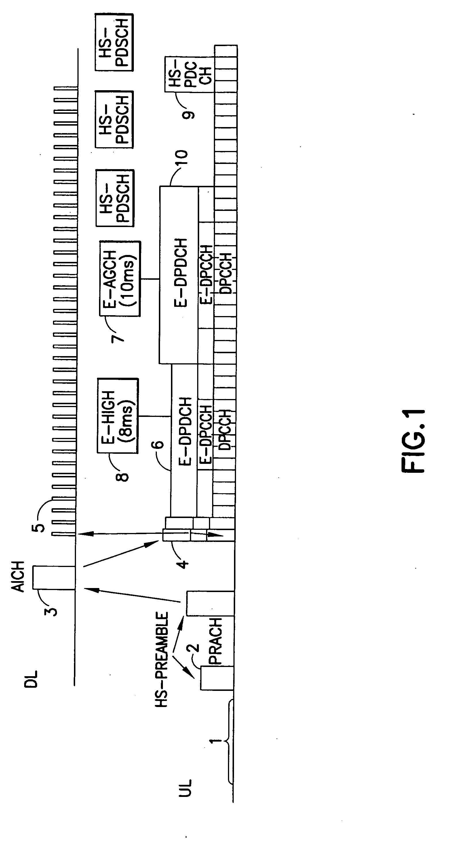
The present invention provides an apparatus and method for transmitting and receiving an indicating acquisition indication channel signature to indicate an enhanced dedicated channel resource for a user equipment. The apparatus includes a transmitter for transmitting the indicating acquisition indication channel signature and a receiver for receiving it. The method involves mapping physical random access signature sequences to one or more acquisition indication channel signatures, selecting an acquisition indication channel signature from a sub-set associated with a physical random access signature sequence, and using the selected acquisition indication channel signature to provide a NACK indication if the enhanced dedicated channel resource is not assigned. The technical effects of the invention include improved efficiency in identifying enhanced dedicated channel resources and improved reliability in transmitting and receiving the indicating acquisition indication channel signature.

Problems solved by technology

The CPCH concept introduced a channel allocation scheme which was based on some level of signature combinations, but dynamic assigning of a dedicated resource was rather limited.
Currently, the existing AICH cannot be used for a dynamic E-DCH resource allocation.
This is because the existing AICH cannot be used dynamically.

Method used


Image

  • Resource Allocation
  • Resource Allocation
  • Resource Allocation

Examples


Embodiment Construction

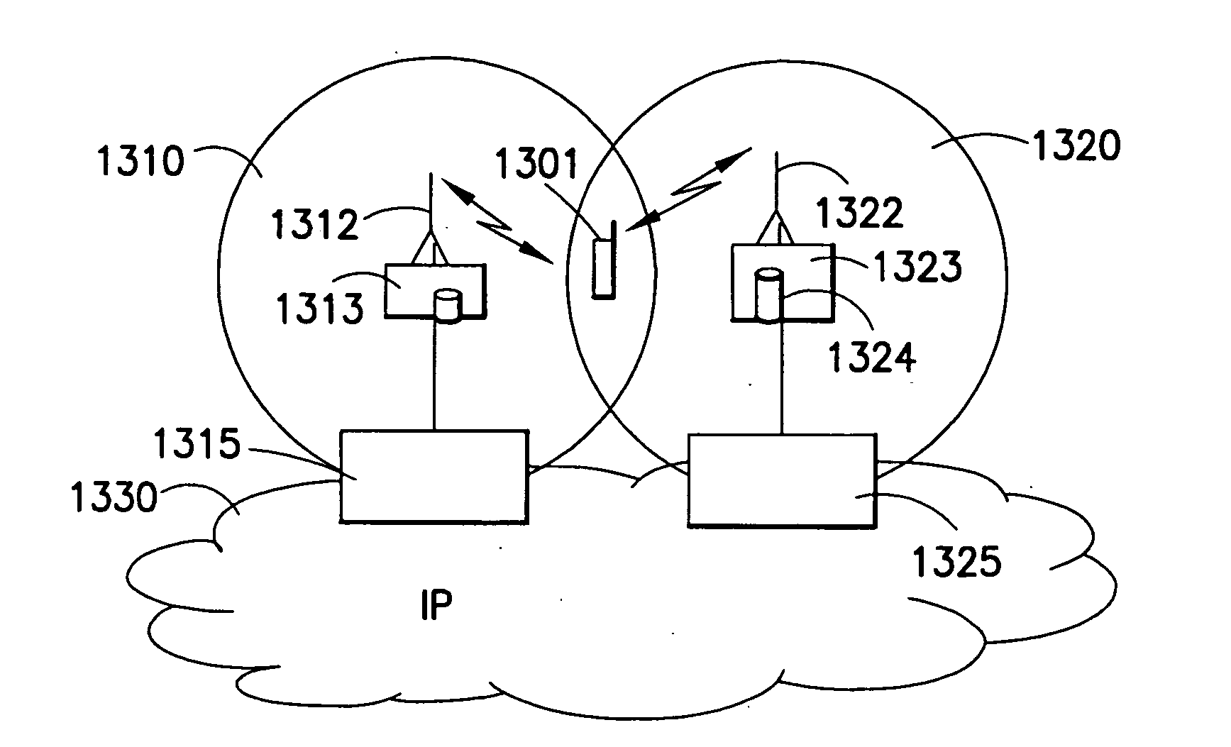
[0078]Reference is made to FIGS. 13 and 14. A communication device can be used for accessing various services and / or applications provided via a communications system. In wireless or mobile systems the access is provided via an access interface between a mobile device 1301 and an appropriate wireless access system 1310 and 1320.

[0079]A mobile device 1301 can typically access wirelessly a communication system via at least one base station 1312 and 1322 or similar wireless transmitter and / or receiver node. Non-limiting examples of appropriate access nodes are a base station of a cellular system and a base station of a wireless local area network (WLAN). Each mobile device may have one or more radio channels open at the same time and may be connected to more than one base station.

[0080]A base station is typically controlled by at least one appropriate controller entity 1313, 1323 so as to enable operation thereof and management of mobile devices in communication with the base station. ...


PUM


Abstract

Apparatus including a transmitter arranged to transmit an indicating acquisition indication channel signature wherein said indicating signature is used to indicate an enhanced dedicated channel resource to be used by a user equipment.

Description

FIELD OF THE INVENTION[0001]The present invention relates to an apparatus and a method for indicating a channel resource.BACKGROUND[0002]The following abbreviations and terms are herewith defined:3GPPthird generation partnership projectACK / NACKacknowledged / not acknowledgedAIacquisition indicatorAICHacquisition indicator channelBCCHbroadcast control channelCQIchannel quality indicatorDPCCHdedicated physical control channelDPCHdedicated physical channelDPDCHdedicated physical data channelDLdownlink (e.g., node B to UE)E-DCHenhanced dedicated physical channelE-DPDCHenhanced dedicated physical data channelE-DPCCHenhanced dedicated physical control channelE-HICHenhanced HICH (also known as E-DCH HARQ AIchannel)E-node Benhanced node B (of an LTE system)E-UTRANenhanced UTRAN, also known as 3.9G or LTEF-DPCHfractional dedicated physical channelHICHhybrid automatic repeat request indicatorchannelHSUPAhigh speed uplink packet accessL1layer 1 (control signalling layer)LTElong term evolution of...

Claims


Application Information

Patent Timeline
Patent Type & Authority Applications(United States)
IPC IPC(8): H04W72/04
CPCH04W74/085H04W74/006H04L5/0055H04W72/0466H04W74/0866
Inventor BARRACLOUGH, KRISTANHAKOLA, SAMI-JUKKARANDALL, DAVIDWIMMER, MARKUS
Owner NOKIA SOLUTIONS & NETWORKS OY
Learn More