
Three dimensional video reproduction apparatus, three dimensional video reproduction system, three dimensional video reproduction method, and semiconductor device for three dimensional video reproduction

Inactive Publication Date: 2010-07-22
PANASONIC INTELLECTUAL PROPERTY MANAGEMENT CO LTD
View PDF5 Cites 115 Cited by
  • Summary
  • Abstract
  • Description
  • Claims
  • Application Information

AI Technical Summary

Benefits of technology

[0012]In view of the aforementioned problems, it is an object to provide a three dimensional video display apparatus capable of improving the usability for viewing by users, in cases where the type of broadcasting is changed over between 2D broadcasting and 3D broadcasting.
[0019]According to the aforementioned respective embodiments, it is possible to improve the usability for viewing by users, in cases where the type of broadcasting is changed over between 2D broadcasting and 3D broadcasting.

Problems solved by technology

Such a parallax barrier method has the problem that the position at which viewing is performed is limited and, also, the barrier obstructs the view.
Further, such a lenticular method has the problem that the resolution is degraded and the lens obstructs the view.
These methods provide the advantages that the contents of broadcasts can be viewed even without glasses and without being doubly blurred even when they are viewed on existing 2D televisions, thereby resulting in a relatively low possibility that users mistakenly determine that there are failures in the televisions.
However, such conventional 3D television apparatuses have problems as follows.
Namely, there is the burden of the changeover.
This causes the users to have an uncomfortable feeling.

Method used


Image

  • Three dimensional video reproduction apparatus, three dimensional video reproduction system, three dimensional video reproduction method, and semiconductor device for three dimensional video reproduction
  • Three dimensional video reproduction apparatus, three dimensional video reproduction system, three dimensional video reproduction method, and semiconductor device for three dimensional video reproduction
  • Three dimensional video reproduction apparatus, three dimensional video reproduction system, three dimensional video reproduction method, and semiconductor device for three dimensional video reproduction

Examples


first embodiment

1. Structure

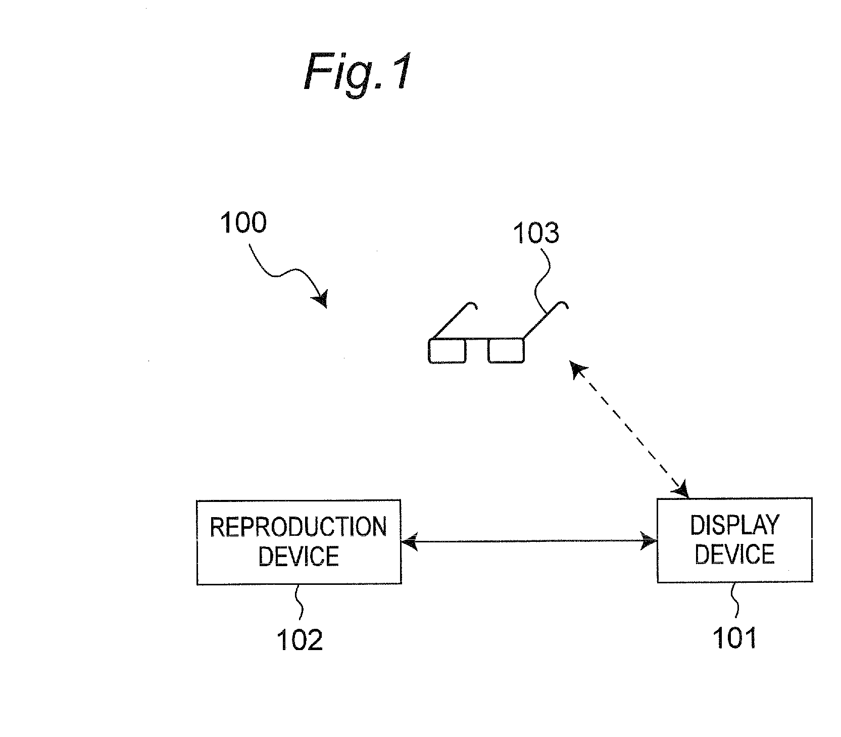
[0038]A first embodiment will be described. FIG. 1 is a block diagram of a three dimensional video display system. The three dimensional video display system 100 includes a three dimensional video display device 101, and a dedicated glasses 103 for viewing three dimensional images being displayed on the three dimensional video display device 101. A reproduction device 102 is connected to the three dimensional video display device 101.

[0039]The reproduction device 102 is, for example, a tuner or a BD / DVD recorder and is adapted to acquire video signals from recording mediums or through networks or broadcasts and further output the video signals.

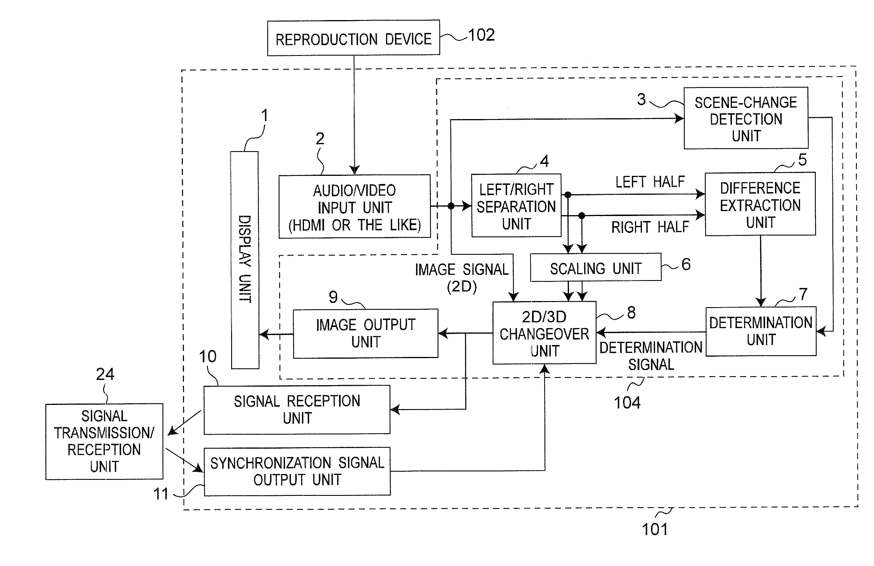
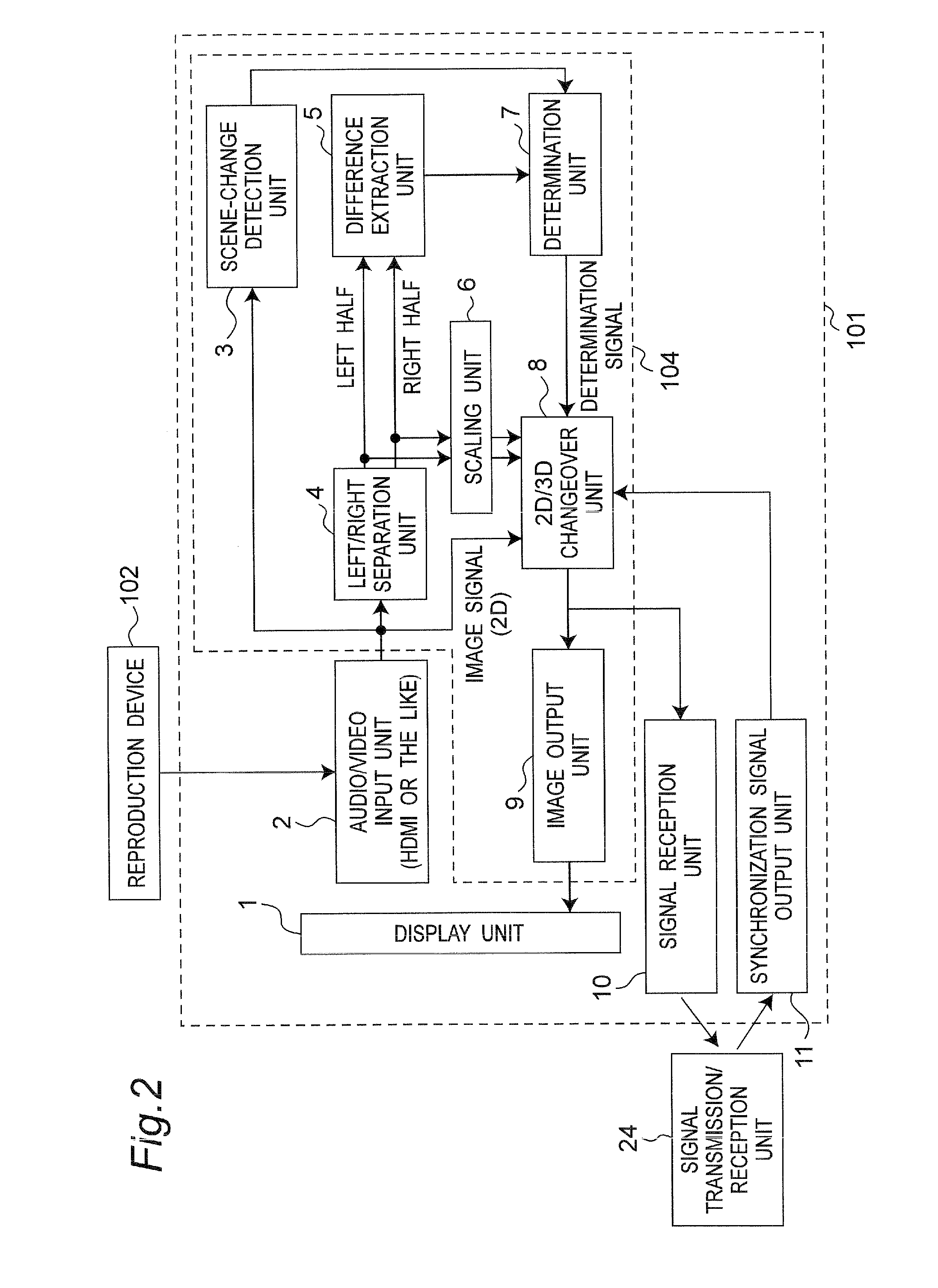
[0040]FIG. 2 is a view illustrating a signal processing block in the three dimensional video display device 101. The three dimensional video display device 101 includes a display unit 1, an audio / video input unit 2, a scene-change detection unit 3, a left / right separation unit 4, a difference extraction unit 5, a scaling unit 6, a ...

second embodiment

[0082]Next, a second embodiment will be described. In the present embodiment, it is assumed that 2D broadcast signal and 3D broadcast signal of a top-and-bottom type are transmitted, as broadcast signal.

[0083]FIG. 8 is a view illustrating a signal processing block in a three dimensional video display device 101 according to the second embodiment. In the second embodiment, there is provided an upper / lower separation unit 34, instead of the left / right separation unit 4 according to the first embodiment.

[0084]The upper / lower separation unit 34 inputs a video signal outputted from an audio / video input unit 2, divides the image indicated by the video signal into two image in the upper and lower sides and outputs video signal indicating the upper half image (the upper side image) and video signal indicating the lower half image (the lower side image).

[0085]A difference extraction unit 5 extracts difference between the upper side image and the lower side image, based on the video signal ou...

third embodiment

[0090]Next, a third embodiment will be described. In the present embodiment, it is assumed that a 2D broadcast signal, and a 3D broadcast signal of both a side-by-side type and a top-and-bottom type are transmitted, as broadcasts.

[0091]FIG. 9 is a view illustrating a signal processing block in a three dimensional video display device 101 according to the third embodiment.

[0092]In the third embodiment, there are provided both the left / right separation unit 4 described in the first embodiment and the upper / lower separation unit 34 described in the second embodiment.

[0093]The left / right separation unit 4 inputs a video signal which is outputted from the audio / video input unit 2, divides the image indicated by the video signal into two image in the left and right sides and, further, outputs a video signal indicating the left-half image (the left side image) and a video signal indicating a right-half image (the right side image).

[0094]The upper / lower separation unit 34 inputs a video sig...


PUM


Abstract

A three dimensional video reproduction apparatus includes a video input unit operable to input a signal for displaying a 2D image or a 3D image; a separation unit operable to divide an image indicated by the signal inputted in the video input unit into two images; a difference extraction unit operable to extract a difference or correlation between the two divided images; a determination unit operable to determine whether the signal inputted in the video input unit is a signal for displaying a 3D image or a signal for displaying a 2D image, based on the output of the difference extraction unit; and a 2D / 3D changeover unit operable to change over an output mode for outputting an image between a 2D mode for displaying a 2D image and a 3D mode for displaying a 3D image, based on the result of the determination by the determination unit.

Description

BACKGROUND ART[0001]1. Technical Field[0002]The technical field is a technique relating to a three dimensional video reproduction apparatus, a three dimensional video reproduction system, a three dimensional video reproduction method and a semiconductor device for three dimensional video reproduction which enable three dimensional viewing using two video signals having a parallax between left and right eyes, such as three dimensional televisions.[0003]2. Related Art[0004]In recent years, there have been rapidly developed techniques for 3D televisions capable of displaying stereoscopic images (three dimensional images (3D images)). As backgrounds thereof, there are hits of 3D movies screened in movie theaters and experimental implementation of 3D broadcasts in some broadcasting stations through BS digital broadcasting. Further, some makers have already commercialized 3D television apparatuses, thereby getting ready for viewing of 3D images in ordinary households.[0005]Generally, ther...

Claims


Application Information

Patent Timeline
IPC IPC(8): H04N13/00H04N13/04
CPCG02B27/2264H04N2213/007H04N13/398H04N13/341H04N13/359H04N2213/008G02B30/24
Inventor KUNO, YOSHIKI
Owner PANASONIC INTELLECTUAL PROPERTY MANAGEMENT CO LTD
Learn More