
Cutter Assembly and Electric Pencil Sharpener

Inactive Publication Date: 2010-07-15
SDI CORPORATION
View PDF4 Cites 13 Cited by
  • Summary
  • Abstract
  • Description
  • Claims
  • Application Information

AI Technical Summary

Benefits of technology

[0011](1) Because the cutter bracket is not connected to the gear assembly of the driving device directly but via a rotating frame, the cutter bracket can be removed from the rotating frame and detached from the body easily. Consequently, a damaged or worn cutter can be repaired or replaced with a new one. Thus, to replace a whole electric pencil sharpener is unnecessary, the cost for using the electric pencil sharpener is lowered.
[0012](2) An air flow can be generated inside the securing frame by fans formed on the rotating frame during the rotation of the rotating frame, so a low pressure is generated inside the securing frame. Consequently, air will be sucked and flow into the securing frame from a side of the driving device to keep dusts or wastes generated during the pencil sharpening process from entering into the driving device. This can keep the driving device from being damaged.
[0013](3) With a post spring mounted on the rotating frame, an automatically axial aligning effect is provided to keep the rotating frame and the cutter assembly rotating in stable.

Problems solved by technology

However, the cutter is easily worn off and damaged after a term of use, and this causes the pencil cannot be sharpened as desire or causes the pencil broken.
In addition, the cutter of the conventional pencil sharpener is connected directly with a transmission device for being connected to and driven by a motor, so the cutter is difficultly and even impossibly detached from the transmission device by a user.
When the unchangeable cutter is damaged, the whole pencil sharpener should be thrown away, but this causes waste of money and usable components in the pencil sharpener.

Method used


Image

  • Cutter Assembly and Electric Pencil Sharpener
  • Cutter Assembly and Electric Pencil Sharpener
  • Cutter Assembly and Electric Pencil Sharpener

Examples


Embodiment Construction

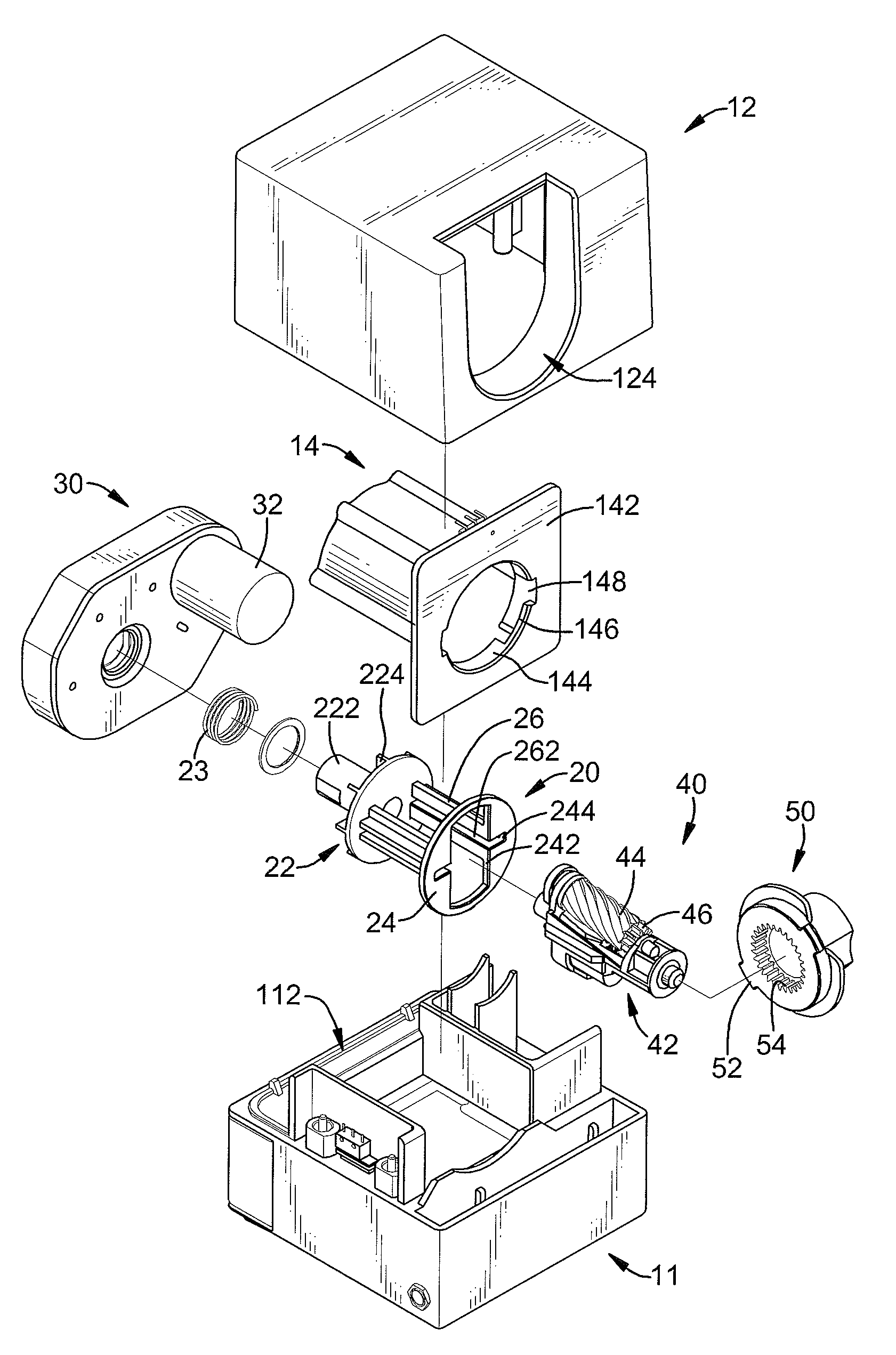
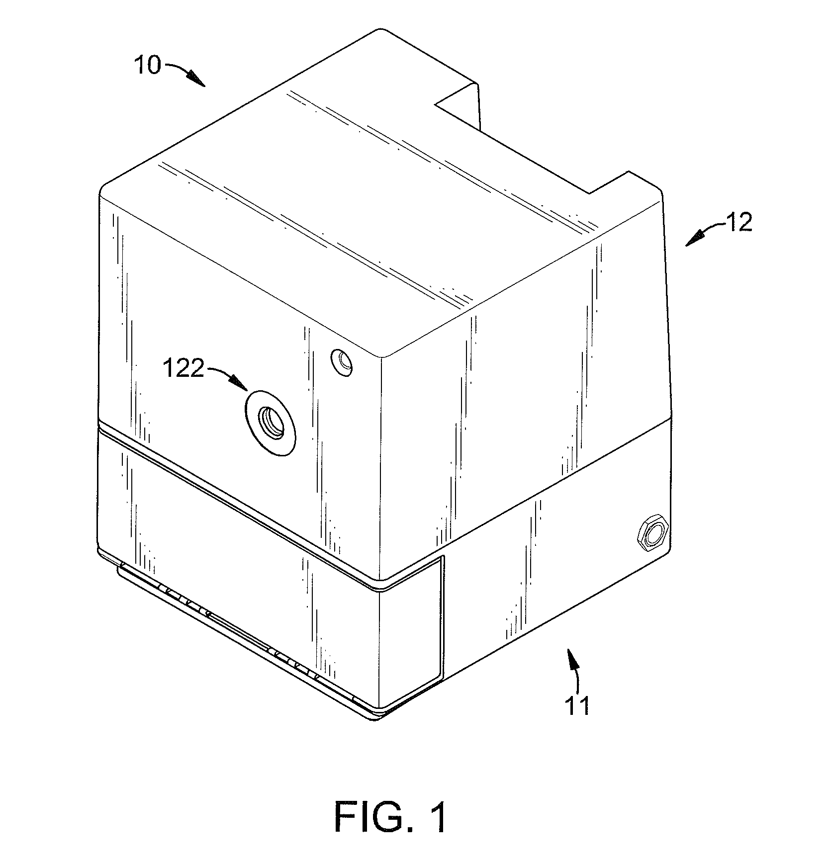
[0027]With reference to FIG. 1, an electric pencil sharpener in accordance with the present invention comprises a body (10), a rotating frame (20), a driving device (30), a cutter assembly (40), a cover (50) and a transmission device.

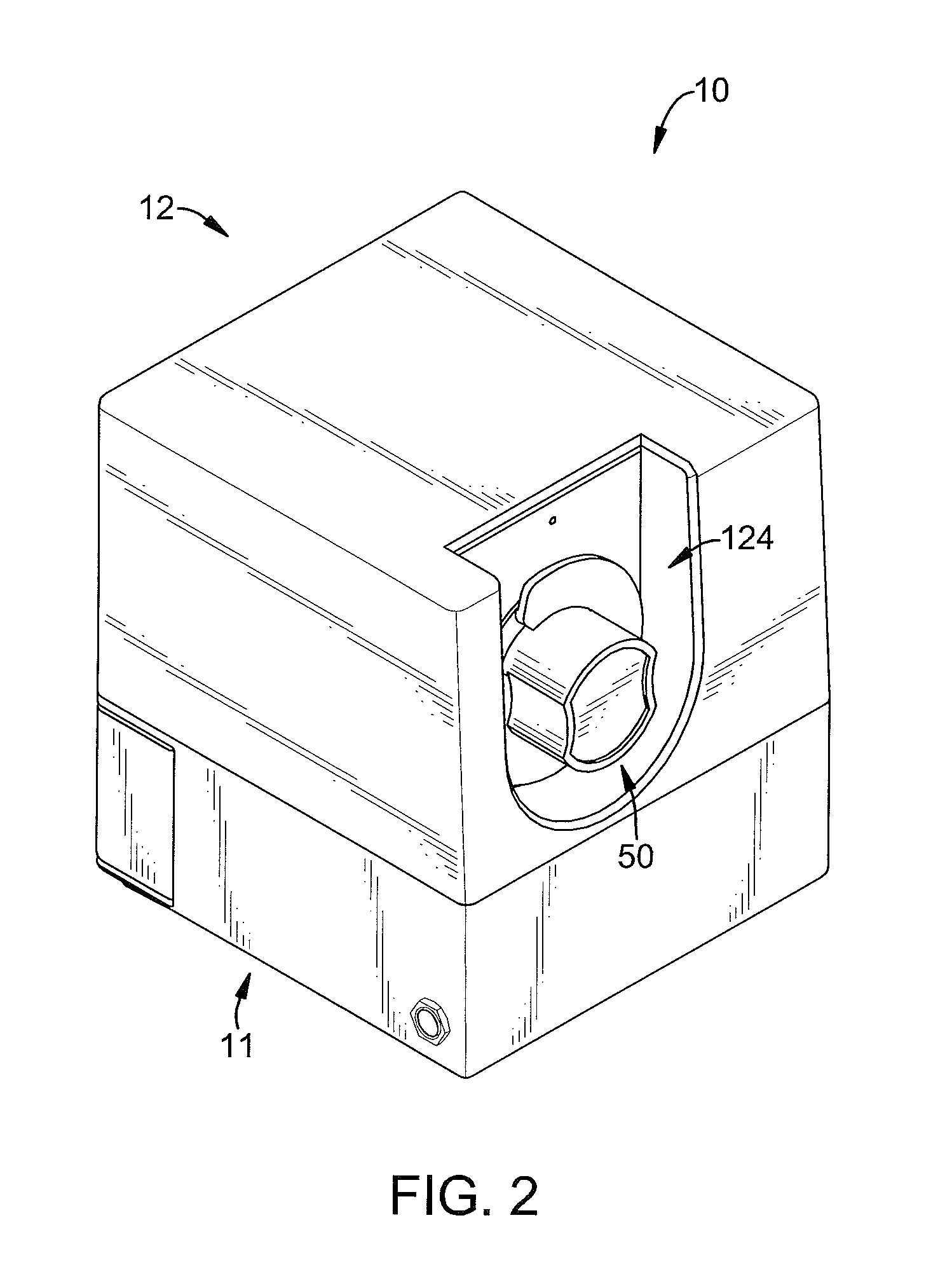
[0028]The body (10) is hollow and may be composed of a base (11) and a casing (12) combined with each other to define a space for holding the other devices inside. The body (10) has a pencil inserting hole (122) and a cutter replacing hole (144) defined respectively in the body (10). The pencil inserting hole (122) and the cutter replacing hole (144) are defined respectively in two sides of the body (10) and may be defined respectively in the front side and the rear side of the casing (12) of the body (10). The body (10) may further has a waste case (112) mounted in the base (11) to hold dusts or wastes generating during a pencil being sharpened.

[0029]The body (10) may further have a securing frame (14) mounted in the casing (12). The securing frame (14...


PUM


Abstract

A cutter assembly for an electric pencil sharpener has a cutter bracket and a cutter. The cutter bracket has a pencil sharpening hole and an engaging structure. The pencil sharpening hole is defined in the cutter bracket for a pencil being inserted into the pencil sharpening hole. The engaging structure is formed on the cutter bracket to engage a rotating frame in the electric pencil sharpener. The cutter is mounted rotatably on the cutter bracket. Accordingly, the cutter assembly is replaceable for the electric pencil sharpener when the cutter of the cutter assembly is damaged or worn off.

Description

BACKGROUND OF THE INVENTION[0001]1. Field of the Invention[0002]The present invention relates to a cutter assembly, and more particularly to a cutter assembly that is replaceable for a pencil sharpener.[0003]2. Description of Related Art[0004]An electrical pencil sharpener can sharpen a pencil with a motor-driven cutter after the pencil being inserted into the pencil sharpener. However, the cutter is easily worn off and damaged after a term of use, and this causes the pencil cannot be sharpened as desire or causes the pencil broken.[0005]In addition, the cutter of the conventional pencil sharpener is connected directly with a transmission device for being connected to and driven by a motor, so the cutter is difficultly and even impossibly detached from the transmission device by a user. When the unchangeable cutter is damaged, the whole pencil sharpener should be thrown away, but this causes waste of money and usable components in the pencil sharpener.[0006]To overcome the shortcomi...

Claims


Application Information

Patent Timeline
IPC IPC(8): B43L23/00
CPCB43L23/06B43L23/008
Inventor YEH, LONG-JYICHUNG, CHIU-HUNGLAI, YAO-JENLIN, HSIEN-CHENGLIN, CHUN-PENG
Owner SDI CORPORATION
Learn More