Compressor device
- Summary
- Abstract
- Description
- Claims
- Application Information
AI Technical Summary
Benefits of technology
Problems solved by technology
Method used
Image

Examples
first embodiment
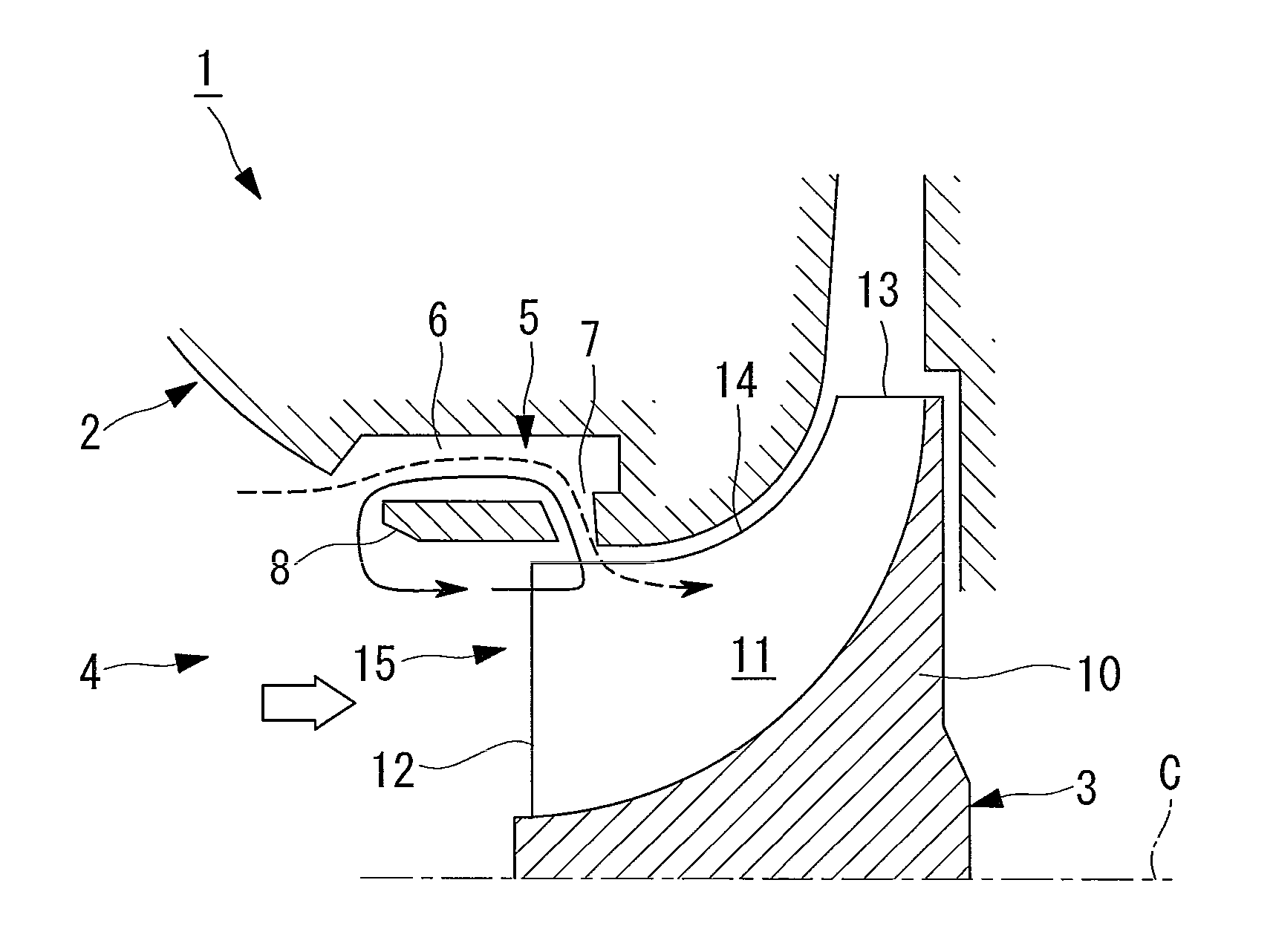
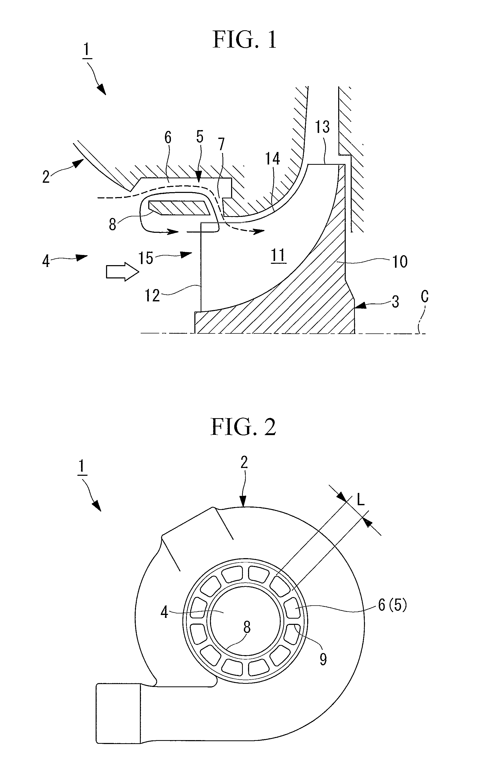
[0031]A first embodiment of the present invention will be described with reference to FIGS. 1 and 2.
[0032]FIG. 1 is a sectional view illustrating the structure of the compressor of a turbocharger according to this embodiment. FIG. 2 is a plan view illustrating the structure of the compressor in FIG. 1.
[0033]In this embodiment, a compressor device according to the invention in this application is described when applied to the compressor of a turbocharger powered by exhaust gas or the like from an internal combustion apparatus such as an engine.
[0034]As shown in FIGS. 1 and 2, the compressor (compressor device) 1 of a turbocharger includes a casing 2 that forms the outer shape and an impeller 3 that compresses air.
[0035]The casing 2 forms the outer shape of the compressor 1 and a turbine (not shown) that constitute the turbocharger of this embodiment. The turbine extracts rotary driving force from the exhaust gas of the above-mentioned internal combustion apparatus or the like, and su...
second embodiment
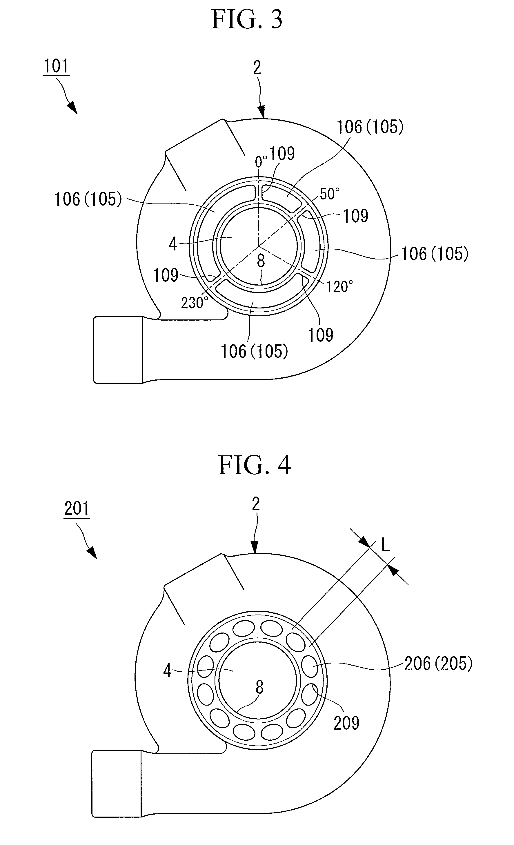
[0063]Referring next to FIG. 3, a second embodiment of the present invention will be described.
[0064]The compressor of this embodiment is similar to the first embodiment in basic structure but different in the structure of the circulating channels. Thus, in this embodiment, only the structure of the circulating channels will be described with reference to FIG. 3, and descriptions of the other components will be omitted.
[0065]FIG. 3 is a schematic diagram illustrating the structure of the circulating channels of the compressor according to this embodiment.
[0066]The same components as those of the first embodiment are given the same reference signs and their descriptions will be omitted.
[0067]As shown in FIG. 3, the casing 2 of the compressor (compressor device) 101 accommodates, in its interior, the impeller 3 (see FIG. 1) rotatably supported about the rotation axis C (see FIG. 1) and is provided with the air intake channel 4 that introduces air, before being compressed, to the impel...
third embodiment
[0076]Referring to FIG. 4, a third embodiment of the present invention will be described.
[0077]The compressor of this embodiment is similar to the first embodiment in basic structure but different in the structure of the circulating channels. Thus, only the structure of the circulating channels will be described with reference to FIG. 4, and descriptions of the other components will be omitted.
[0078]FIG. 4 is a schematic diagram illustrating the structure of the circulating channels of the compressor according to this embodiment.
[0079]The same components as those of the first embodiment are given the same reference signs and their descriptions will be omitted.
[0080]As shown in FIG. 4, the casing 2 of the compressor (compressor device) 201 accommodates, in its interior, the impeller 3 (see FIG. 1) rotatably supported about the rotation axis C (see FIG. 1) and is provided with the air intake channel 4 that introduces air, before being compressed, to the impeller 3 and circulating chan...
PUM
 Abstract
Description
Claims
Application Information
 - R&D
- Intellectual Property
- Life Sciences
- Materials
- Tech Scout
- Unparalleled Data Quality
- Higher Quality Content
- 60% Fewer Hallucinations
Browse by: Latest US Patents, China's latest patents, Technical Efficacy Thesaurus, Application Domain, Technology Topic, Popular Technical Reports.
© 2025 PatSnap. All rights reserved.Legal|Privacy policy|Modern Slavery Act Transparency Statement|Sitemap|About US| Contact US: help@patsnap.com