Strap adjuster

a technology of strap adjuster and adjuster, which is applied in the direction of snap fasteners, metal working devices, press-button fasteners, etc., can solve the problems of inconvenient use, interference, damage to clothes placed under, etc., and achieve the effect of improving the adhesion between the lower surface of the strap adjuster and an object to be contacted and efficient pressing

Inactive Publication Date: 2010-07-08
PAIK JISOOK
View PDF10 Cites 31 Cited by
  • Summary
  • Abstract
  • Description
  • Claims
  • Application Information

AI Technical Summary

Benefits of technology

[0020]Accordingly, the present invention has been made in an effort to solve the problems occurring in the related art, and an object of the present invention is to provide a strap adjuster which is formed with recessions on both widthwise side surfaces thereof so that the strap adjuster can be easily grasped and moved by fingers, thereby ensuring manipulation convenience.
[0021]Another object of the present invention is to provide a strap adjuster in which protrusion is minimized so that, when the strap adjuster is coupled to a strap, interference between the strap adjuster and the human body or an external item can be reduced, thereby preventing inconvenience or annoyance from being caused to a user due to the interference.
[0022]Still another object of the present invention is to provide a strap adjuster which has close contact parts to stably press a strap so that the fastened state of the strap can be reliably maintained.

Problems solved by technology

However, in the conventional strap adjuster 1, inconvenience is caused due to the substantial thickness of the frame 2 when the strap adjuster 1 is employed in knapsacks or clothes.
In particular, in the case where the strap adjuster 1 is employed in the shoulder strap of a knapsack, as the strap adjuster 1 comes into contact with the human body, interference is caused between the strap adjuster 1 and the human body, and damage to the clothes which are placed under the strap adjuster 1 can be caused.
Also, the strap adjuster 1 may not be kept fixed on the strap S and is likely to be easily moved due to contact with the human body or an external item so that the fixed state of the strap adjuster 1 cannot be stably maintained.
Meanwhile, the strap adjuster 1, which is installed on the strap S, is slid on the strap S by being grasped using fingers so as to adjust the effective length of the strap S. In this regard, even though the strap adjuster 1 has a substantial thickness even causing the interference as described above, the strap adjuster 1 is structured so that it is inconvenient to grasp the strap adjuster 1 using fingers.
That is to say, while it is the norm that both side surfaces of the strap adjuster 1 are grasped and the strap adjuster 1 is moved in the lengthwise direction of the strap S, since the strap adjuster 1 is small-sized and the side walls of the strap adjuster 1 are thin and have insufficient length, it is inconvenient to grasp the strap adjuster 1 using fingers.
This type of strap adjuster 11 also suffers from drawbacks in that it is inconvenient to grasp and move the strap adjuster 11 using fingers, interference between the strap adjuster 11 and the human body or an external item is likely to be caused, and the fixed state of the strap adjuster 11 on the strap may not be stably maintained.
That is to say, although various strap adjusters, which are structured in such a way as to define slots by the presence of one or more support bars as shown in FIGS. 1 through 4 so as to allow a strap to be passed through the slots have been disclosed in the art, they encounter the problems as described above.
As a result, in the conventional strap adjusters, sliding manipulation of the strap adjusters is inconvenient, the fixed state of the strap adjusters cannot be stably maintained due to the interference between the strap adjusters and the human body or an external item, and annoyance is likely to be caused due to the contact with the strap adjusters and the human body.

Method used


Image

  • Strap adjuster
  • Strap adjuster
  • Strap adjuster

Examples


Embodiment Construction

[0044]Reference will now be made in greater detail to preferred embodiments of the invention, examples of which are illustrated in the accompanying drawings. Wherever possible, the same reference numerals will be used throughout the drawings and the description to refer to the same or like parts.

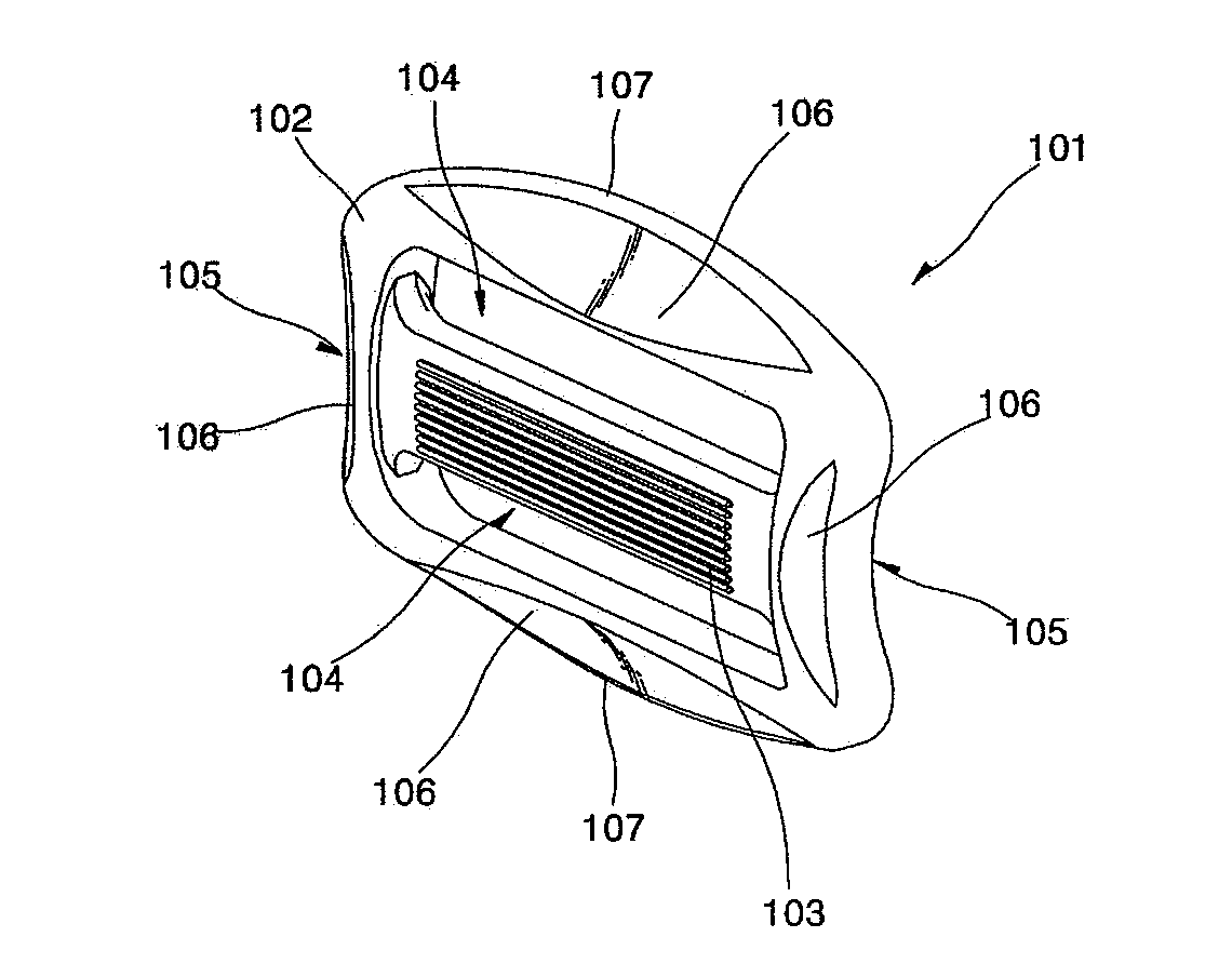
[0045]FIG. 5 is a perspective view illustrating a strap adjuster in accordance with an embodiment of the present invention, FIG. 6 is a front view of FIG. 5, and FIG. 7 is a side sectional view illustrating a state in which a strap is fitted through the strap adjuster. Referring to these drawings, a strap adjuster 101 has a quadrangular frame 102 which defines a space therein, and a support bar 103 which is formed in the middle of the space defined in the frame 102 to extend in a transverse direction. Slots 104 are defined between the support bar 103 and the frame 102 over and under the support bar 103 so that a strap S can be fitted through the slots 104.

[0046]The slots 104 defined in the s...


PUM


Abstract

A strap adjuster has a quadrangular frame; a plurality of slots defined in the frame to extend in a transverse direction such that a strap can be fitted through the slots; and at least one support bar formed between the slots, wherein recessions are formed on both widthwise side surfaces, respectively, of the frame such that the frame can be easily grasped using fingers.

Description

BACKGROUND OF THE INVENTION[0001]1. Field of the Invention[0002]The present invention relates, in general, to a strap adjuster which is used to be mounted to a strap installed on knapsacks, bags, clothes, helmets, etc. so as to adjust the effective length of the strap or fix the strap adjuster at a desired position on the strap, and more particularly, to a strap adjuster which is configured to be conveniently moved on a strap and has improved adhesibility to the strap to be stably maintained in a fixed state without substantial protrusion.[0003]2. Description of the Related Art[0004]In general, straps are installed on knapsacks, bags, hats, clothes, etc. as the occasion demands. A strap adjuster is mounted to a strap so that the strap can be tightened or the effective length of the strap can be adjusted by virtue of the strap adjuster.[0005]The strap adjuster has a frame which has a substantially rectangular configuration. A support bar is formed in the frame in such a way as to con...

Claims


Application Information

Patent Timeline
IPC IPC(8): A44B11/00
CPCA44B11/04Y10T24/40B26D1/04B26D5/10B26D7/20B26D7/28
Inventor PAIK, JISOOK
Owner PAIK JISOOK
Why Eureka
Try Eureka