Apparatus and method for driving 2-phase srm motor

a technology of resistance motor and apparatus, which is applied in the direction of electronic commutation motor control, motor/generator/converter stopper, dynamo-electric converter control, etc., can solve the problems of not being able to normally drive the srm, not being able to generate torque sufficiently, and the conventional ar

Inactive Publication Date: 2010-06-24
LG ELECTRONICS INC
View PDF11 Cites 1 Cited by
  • Summary
  • Abstract
  • Description
  • Claims
  • Application Information

AI Technical Summary

Problems solved by technology

However, the conventional art has the following problems.
Accordingly, a torque is not sufficiently generated thus not to normally drive the SRM.
Accordingly, a sufficient amount of torque is not generated at the time of driving the SRM at a high speed.

Method used


Image

  • Apparatus and method for driving 2-phase srm motor
  • Apparatus and method for driving 2-phase srm motor
  • Apparatus and method for driving 2-phase srm motor

Examples


Embodiment Construction

[0029]FIG. 7 is a block diagram showing a configuration of an apparatus for driving a 2-phase SRM according to the present invention.

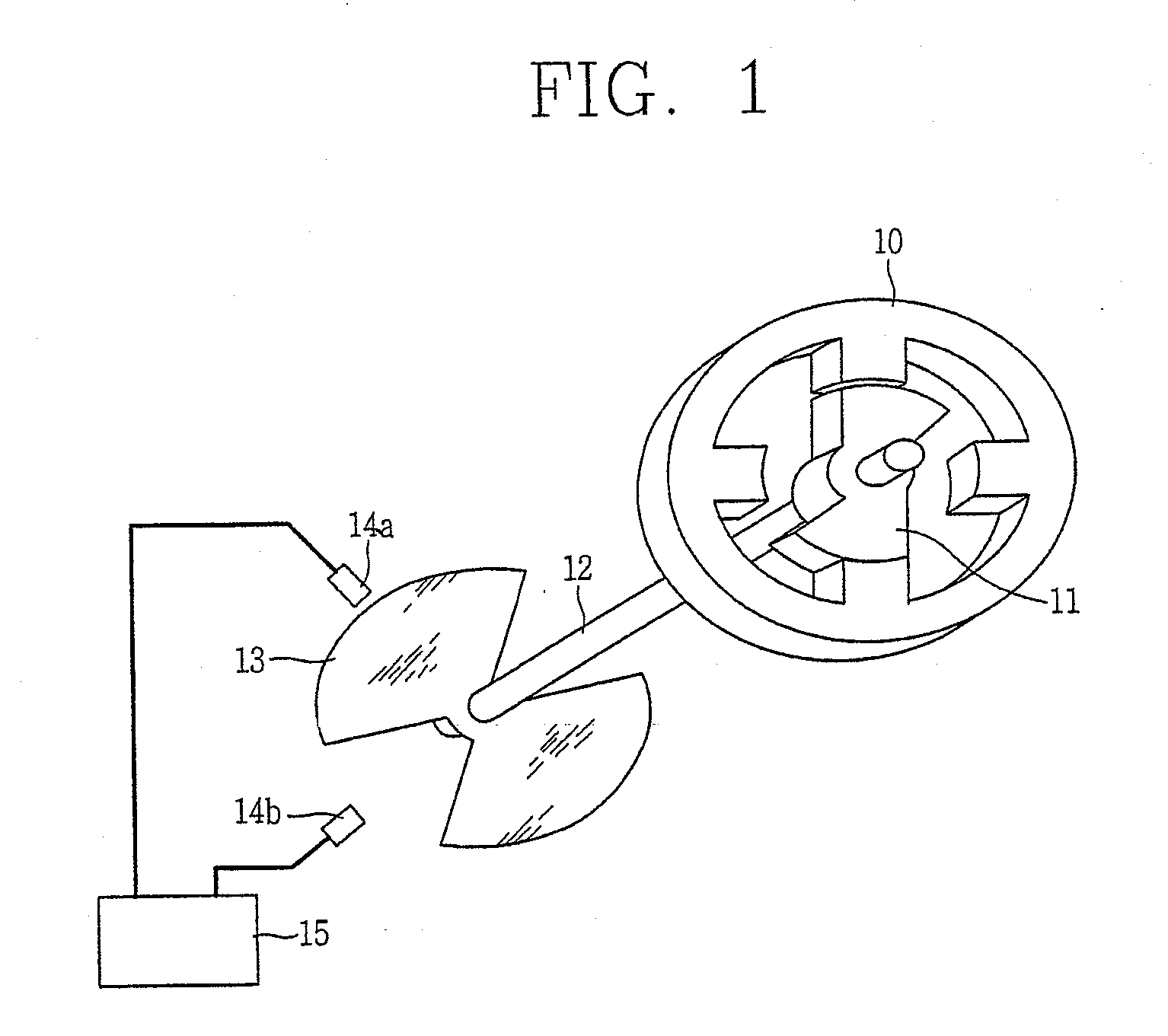
[0030]As shown, the apparatus for driving a 2-phase SRM according to the present invention comprises an initializing sensor 71a, a driving sensor 71b, a microprocessor 72, an oscillator 73 and a multiplying unit 74.

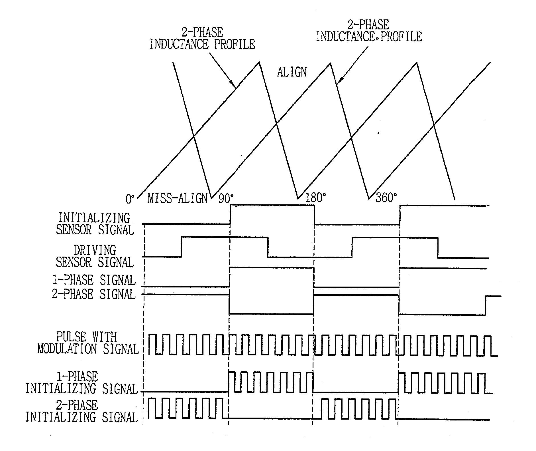
[0031]The initializing sensor 71a detects a position of a rotor of the 2-phase SRM at the time of an initial driving, and outputs an initializing sensor signal based on the detected result.

[0032]The driving sensor 71b detects a position of a rotor of the 2-phase SRM at the time of a normal driving, and outputs a driving sensor signal based on the detected result.

[0033]The microprocessor 72 generates 1-phase and 2-phase signals from the initializing sensor signal and the driving sensor signal outputted from the initializing sensor 71a and the driving sensor 71b.

[0034]When the 2-phase SRM has an rpm more than a preset rpm after being initiall...


PUM


Abstract

Disclosed is an apparatus and method for driving a 2-phase SRM. The method comprises initializing 2-phase based on a detected position of a rotor by an initializing sensor at the time of an initial driving, and normally driving 2-phase based on a detected position of the rotor by a driving sensor. Accordingly, a sufficient amount of torque is generated when the 2-phase SRM is driven at a high speed. The apparatus comprises an initializing sensor which detects each position of each phase of a 2-phase SRM, and generates an initializing sensor signal based on the detected result; a driving sensor which detects each position of each phase of the 2-phase SRM, and generates a driving sensor signal based on the detected result; and a microprocessor which initially drives the 2-phase SRM based on the initializing sensor signal at the time of an initial driving, and normally drives the 2-phase SRM based on the driving sensor signal at the time of a normal driving.

Description

TECHNICAL FIELD[0001]The present invention relates to a 2-phase SRM (switched reluctance motor), and more particularly, to an apparatus and method for driving a 2-phase SRM by individually using an initializing sensor for an initial driving and a driving sensor for a normal driving.BACKGROUND ART[0002]In the conventional method for driving a 2-phase SRM, two position sensors are used to detect each position of a rotor, and generated sensor signals serve to initialize and drive each phase.[0003]FIG. 1 is a view schematically showing a construction for detecting a sensor signal of a 2-phase SRM. As shown, the 2-phase SRM comprises a 4-pole stator 10, a 2-phase rotor 11, a rotor shaft 12 connected to the center of the rotor 11 for transmitting a rotary motion of the rotor, a 2-phase shutter 13 rotatably connected to the rotor shaft 12, 1-phase and 2-phase sensors 14a and 14b for detecting a position of the shutter 13, and a sensor signal generator 15 for generating 1-phase and 2-phase ...

Claims


Application Information

Patent Timeline
Patent Type & Authority Applications(United States)
IPC IPC(8): H02P6/20
CPCH02P25/08H02P6/008H02P1/163
Inventor KIM, SANG-YOUNG
Owner LG ELECTRONICS INC
Why Eureka
Try Eureka