
Needle insertion systems and methods

Active Publication Date: 2010-06-17
MEDTRONIC MIMIMED INC
View PDF47 Cites 207 Cited by
  • Summary
  • Abstract
  • Description
  • Claims
  • Application Information

AI Technical Summary

Benefits of technology

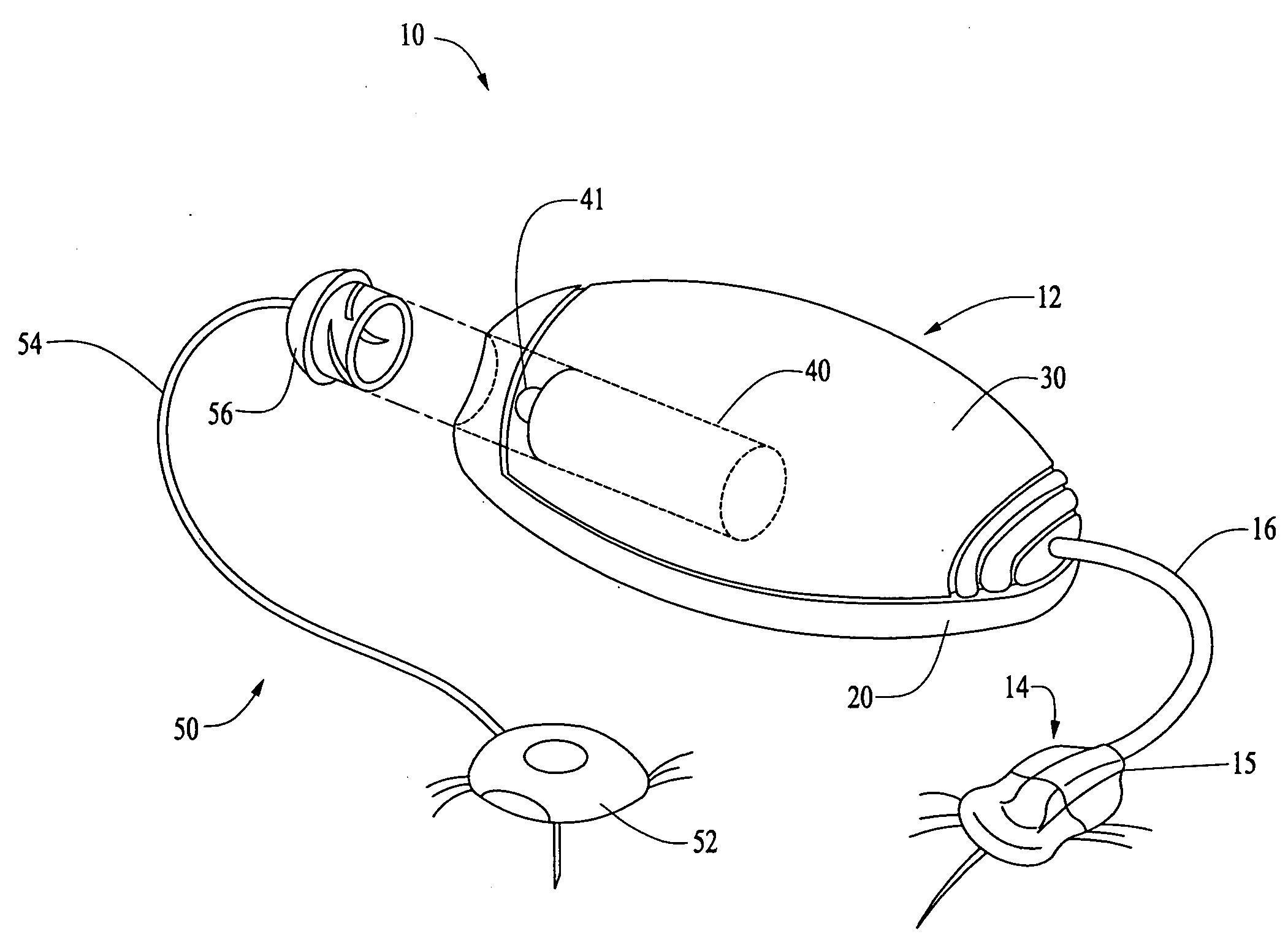
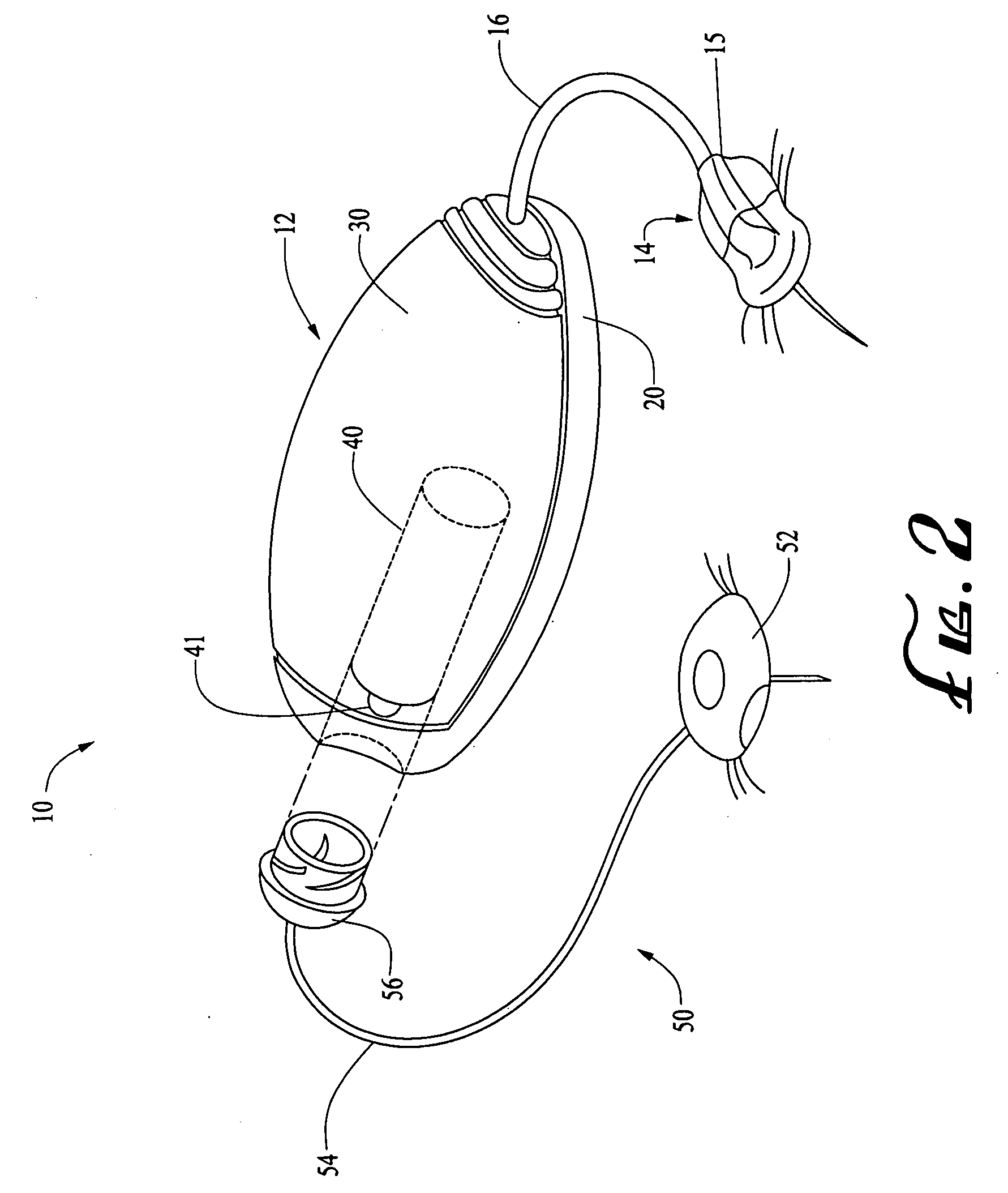
[0032]A medical device in accordance with an embodiment of the present invention may include, but is not limited to, a medical monitoring or treatment device, a housing, and a magnifying material. The medical monitoring or treatment device may be configured to provide a monitoring or treatment operation on a user. The medical monitoring or treatment device may be operable with an insertion needle. The housing may be adapted to be secured to the user for supporting the medical monitoring or treatment device during operation of the medical monitoring or treatment device. The magnifying material may be arranged on the housing for increasing visibility of an injection site on skin of the user when piercing the skin of the user with the insertion needle.
[0036]A method of making a medical device in accordance with an embodiment of the present invention may include, but is not limited to any one or combination of, (i) providing a medical monitoring or treatment device configured to provide a monitoring or treatment operation on a user, the medical monitoring or treatment device operable with an insertion needle; (ii) providing a housing adapted to be secured to the user for supporting the medical monitoring or treatment device during operation of the medical monitoring or treatment device; and (iii) arranging a magnifying material on the housing for increasing visibility of an injection site on skin of the user when piercing the skin of the user with the insertion needle.

Problems solved by technology

In contexts in which the hollow tubing is connected to the user-patient through a hollow needle that pierces the user-patient's skin, a manual insertion of the needle into the user-patient can be somewhat traumatic to the user-patient.

Method used


Image

  • Needle insertion systems and methods
  • Needle insertion systems and methods
  • Needle insertion systems and methods

Examples


Embodiment Construction

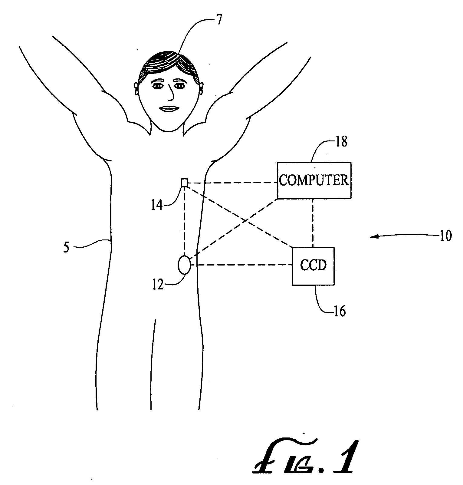
[0063]FIG. 1 illustrates a generalized representation of a system 10 in accordance with an embodiment of the present invention. The system 10 includes a delivery device 12. The system 10 may further include a sensing device 14, a command control device (CCD) 16, and a computer 18. In various embodiments, the delivery device 12 and the sensing device 14 may be secured at desired locations on the body 5 of a patient or user-patient 7. The locations at which the delivery device 12 and the sensing device 14 are secured to the body 5 of the user-patient 7 in FIG. 1 are provided only as representative, non-limiting, examples.

[0064]The system 10, delivery device 12, sensing device 14, CCD 16 and computer 18 may be similar to those described in the following U.S. patent applications that were assigned to the assignee of the present invention, however, with a reservoir and plunger configuration such as described herein with reference to FIGS. 7-8C, where each of following patent applications...


PUM

PropertyMeasurementUnit
Forceaaaaaaaaaa
Adhesion strengthaaaaaaaaaa
Flexibilityaaaaaaaaaa

Abstract

A housing may have a needle, plunger, and bias mechanism supported within the housing by a tab configured to retain the plunger in position and to allow the plunger to move under bias force imparted by the bias mechanism to move the needle to an insert position when the tab is removed. A base and a structure may be configured for relative movement there between and may be adapted to be secured to a user with a cannula extending through a body of the structure into the user during use of a medical device. A housing may be adapted to be secured to a user to support a medical device operable with an insertion needle, the housing having a magnifying material for increasing visibility of an injection site.

Description

BACKGROUND OF THE INVENTION[0001]Certain chronic diseases may be treated, according to modern medical techniques, by delivering a medication or other substance to a user-patient's body, either in a continuous manner or at particular times or time intervals within an overall time period. For example, diabetes is a chronic disease that is commonly treated by delivering defined amounts of insulin to the user-patient at appropriate times. Some common modes of providing an insulin therapy to a user-patient include delivery of insulin through manually operated syringes and insulin pens. Other modern systems employ programmable pumps to deliver controlled amounts of insulin to a user-patient.[0002]Pump type delivery devices have been configured in external devices (that connect to a user-patient) or implantable devices (to be implanted inside of a user-patient's body). External pump type delivery devices include devices designed for use in a generally stationary location (for example, in a...

Claims


Application Information

Patent Timeline
IPC IPC(8): A61M5/32A61M5/20B23P11/00
CPCA61M5/1413A61M5/14248A61M5/3287A61M2005/14252A61M2005/1426Y10T29/49826A61M2005/1585A61M2205/58A61M2205/583A61M2205/585A61M2205/586A61M2005/1581A61M5/2033A61M2005/2073
Inventor HANSON, IAN B.KAVAZOV, JULIAN D.
Owner MEDTRONIC MIMIMED INC
Learn More