
Aircraft radial tire

a technology of radial tires and airframes, which is applied in the direction of inflatable tyres, tyre beads, transportation and packaging, etc., can solve the problems of not being able to meet the requirements of passenger or truck tires, extreme operating conditions of aircraft tires, and tires that are subject to much greater deflection than passenger or truck tires

Active Publication Date: 2010-06-17
THE GOODYEAR TIRE & RUBBER CO
View PDF15 Cites 13 Cited by
  • Summary
  • Abstract
  • Description
  • Claims
  • Application Information

AI Technical Summary

Benefits of technology

[0015]“Chafers” refers to narrow strips of material placed around the outside of the bead to protect cord plies from the rim, distribute flexing above the rim, and to seal the tire.

Problems solved by technology

Aircraft tires are subject to extreme operating conditions due to the heavy load per tire coupled with the high speed of the aircraft.
Because of the heavy loading, the tires are subject to much greater deflection that passenger or truck tires.
This has not been possible in the past because they have more deflection in the sidewall due to bending under loading.
As a result, radial tires may have an increased heat generation and mechanical fatigue in the bead area of the tire.
There may also be problems of bead cracking and scuffing in the bead region, as well as rubber deformation under the bead core.

Method used


Image

  • Aircraft radial tire
  • Aircraft radial tire
  • Aircraft radial tire

Examples


Embodiment Construction

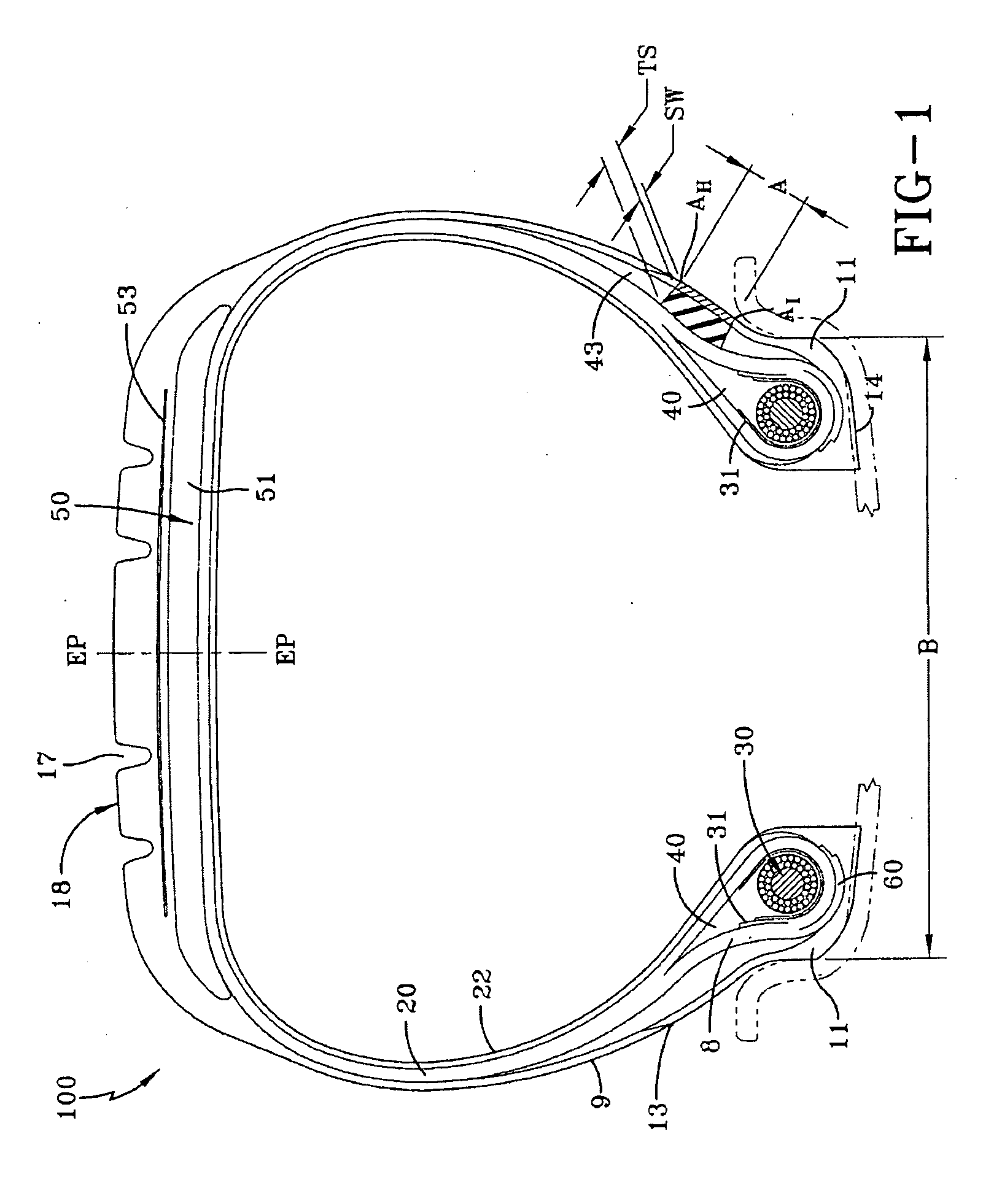
[0029]With reference to FIG. 1, a cross-sectional view of a radial ply tire 100 is shown. The tire 100, as illustrated, is a construction for use as an aircraft tire. The tire 100 by way of example is a radial aircraft tire exposed to high internal pressures and tremendous loads. The invention is not limited to an aircraft tire, and may be used on other tires such as earthmover, commercial truck and off the road tires.

[0030]The tire 100 is a radial ply tire of the tubeless type construction. The tire 100 has an air imperious inner liner 22 which contains fluid or air under pressure. Radially outward of the inner liner 22 are one or more radial plies 20. Each ply 20 extends from an annular tensile member commonly referred to as a bead core 30. As shown the plies 20 may wrap about the bead core 30 either turning axially out and up forming a ply turnup or alternately turning axially in and under the bead core 30. The plies may be anchored to the bead utilizing other configurations know...


PUM


Abstract

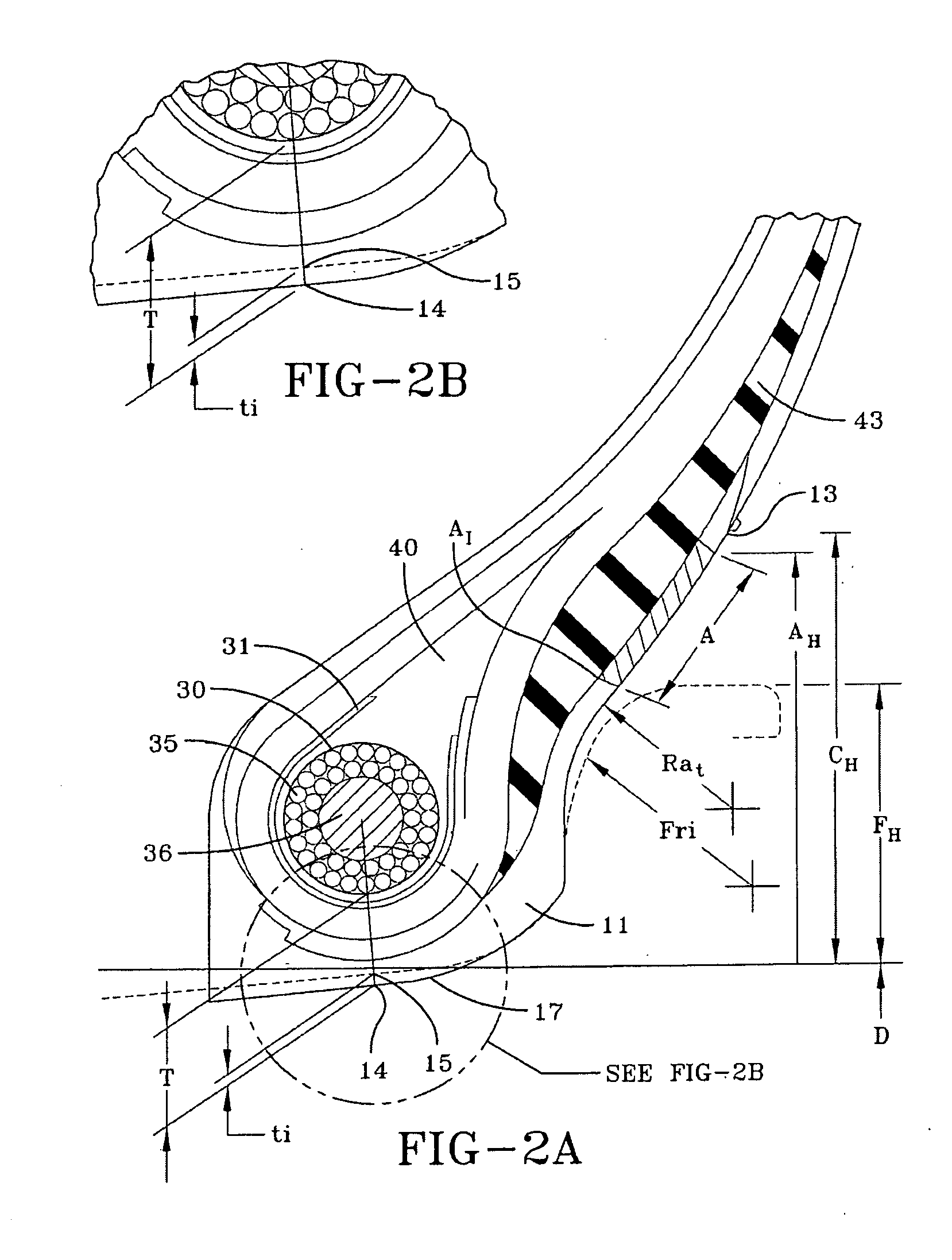
A pneumatic radial aircraft tire is described having a B / A ranging between 60-70%, wherein B is the width of the tire between the wheel flange, and A is the inflated tire width under rated pressure. The tire may further optionally include a tire bead portion having a Ra / Fr1 relationship which ranges from about 1 to about 2.1, wherein: Ra is the tire heel radius at uninflated and in an new and unused condition, and Fr1 is the wheel flange elliptical radius at the heel section of the tire. The tire may further optionally include a SW / TS ratio which ranges from about 0.1 to about 0.5, wherein SW is the chafer gauge at area A, TS is the total sidewall rubber gauge at area A, wherein A is defined as the region in the sidewall that has a lower radial endpoint defined by the point of contact between the flange and the tire at inflated, unloaded condition, and an upper radial endpoint Ah defined by the tire wheel flange point of contact when the tire is at inflated, and at 100% rated load.

Description

[0001]This invention relates in general to radial ply tires, and more particularly to tires subjected to very heavy loads and high pressures.BACKGROUND OF THE INVENTION[0002]Aircraft tires are subject to extreme operating conditions due to the heavy load per tire coupled with the high speed of the aircraft. Because of the heavy loading, the tires are subject to much greater deflection that passenger or truck tires.[0003]Aircraft tires have two common constructions: bias and radial. Over 80% of aircraft tires are bias, which means they have a casing made of layers of alternate layers of ply that are at alternate angles substantially less than 90 degrees relative to the center line of the tread. However, radial tires are becoming more common as airframe manufacturers seek lighter weight. Radial tires are like passenger tires in that they have the ply oriented at substantially 90 degrees relative to the tread centerline. Aircraft tires come in a range of sizes, however the H size range...

Claims


Application Information

Patent Timeline
Patent Type & Authority Applications(United States)
IPC IPC(8): B60C9/18B60C9/00
CPCB60C3/04B60C15/024B60C15/04B60C15/06B60C2200/02Y10T152/10828Y10T152/10819B60C2015/0614Y10T152/10783Y10T152/10792B60C2015/0621B60C2015/0617B60C15/0607
Inventor UEYOKO, KIYOSHIALSOBROOK, CLARENCE BYRDDAS, BADAL
Owner THE GOODYEAR TIRE & RUBBER CO
Learn More