
Collapsible pan

Inactive Publication Date: 2010-06-03
EDISON NATION
View PDF1 Cites 18 Cited by
  • Summary
  • Abstract
  • Description
  • Claims
  • Application Information

AI Technical Summary

Benefits of technology

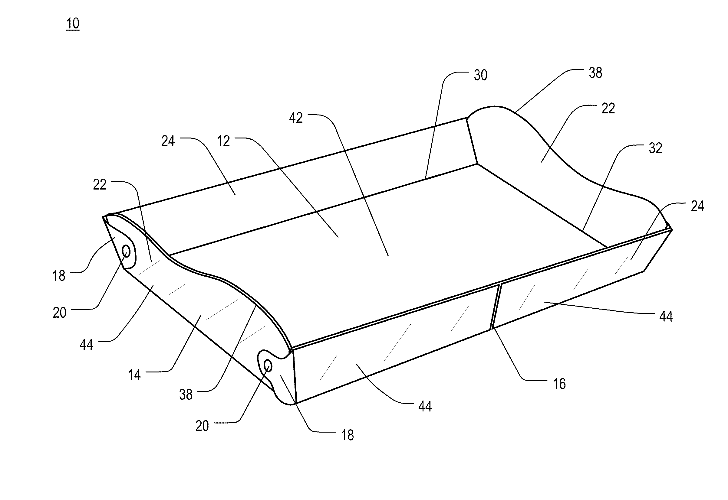
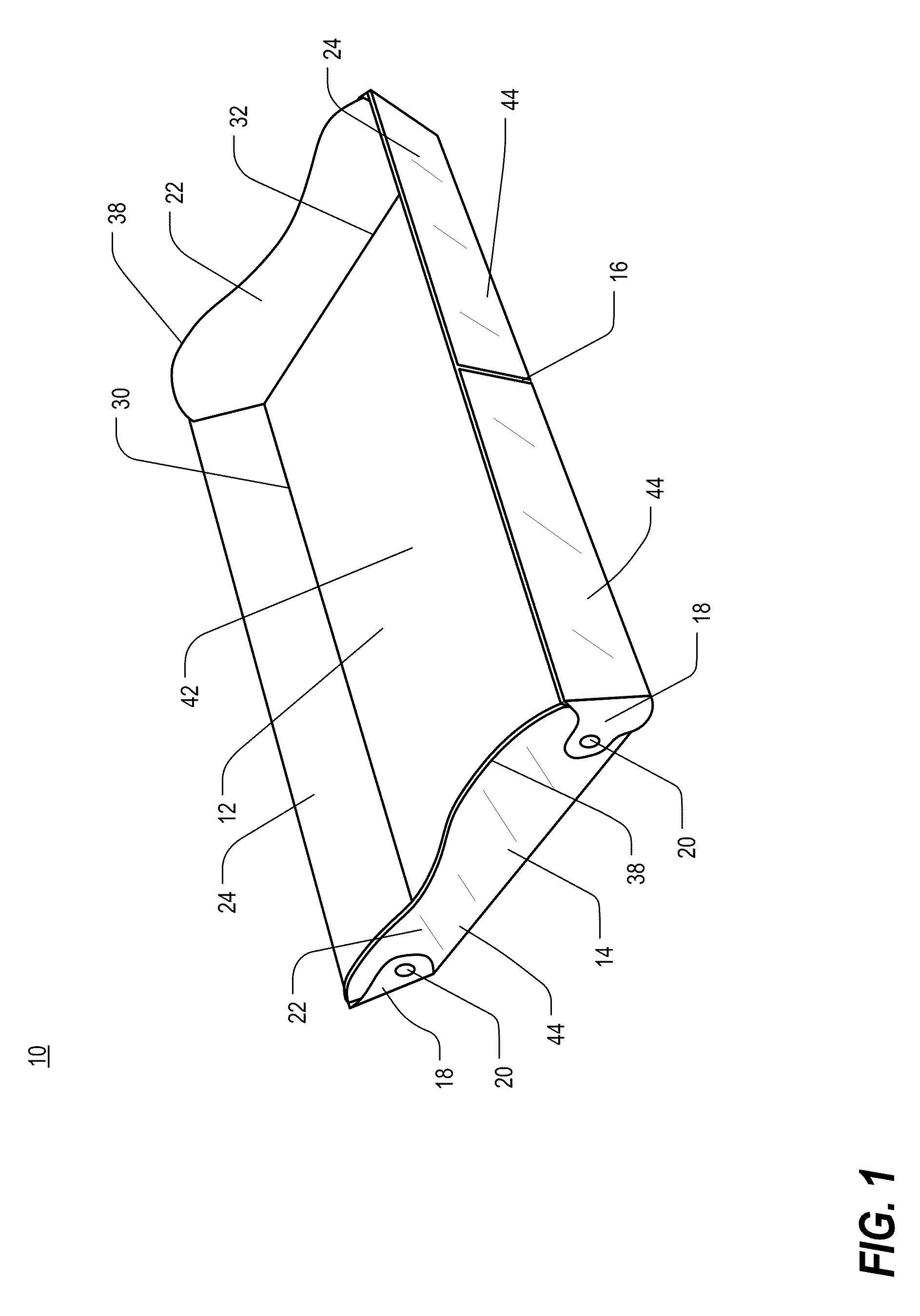
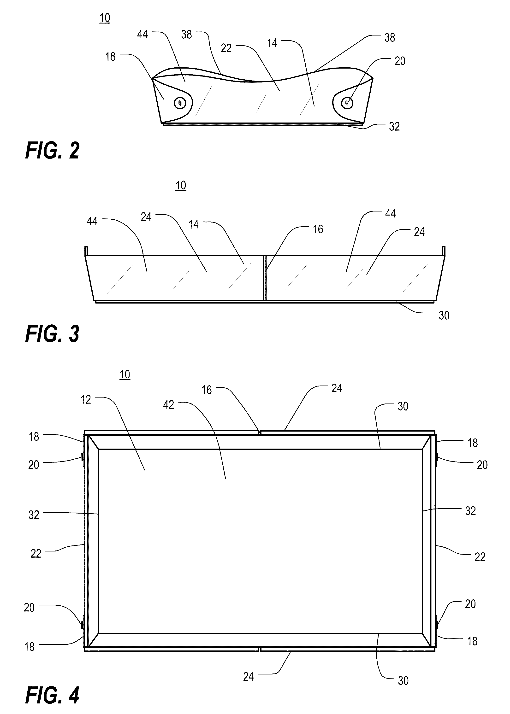
[0016]Broadly defined, the present invention according to still another aspect includes a collapsible pan that includes a base plate, a plurality of side plates, and a flexible web to interconnect the base plate with the respective side plates at edges thereof. The flexible web facilitates pivotable movement of the side plates relative to the base plate, thereby permitting adjustment of the collapsible pan between a use configuration, whereby the side plates are arranged generally upright relative to the base plate to define a partial enclosure, and a collapsed configuration, whereby the side plates are arranged to lay generally flat relative to the base plate.
[0023]In further features of this aspect, the collapsible pan may further comprise a plurality of tabs at opposite ends of at least some of the plurality of side portions for attaching adjacent side portions together in the use configuration; adjacent side portions may be releasably attached together when in the use configuration so as to permit quick release of the tabs, thereby freeing the plurality of side portions for pivotable adjustment; an interior baking surface of each of the base portion and the plurality of side portions may be comprised of a synthetic polymer; and the synthetic polymer may be a silicone-based polymer.
[0024]Broadly defined, the present invention according to still another aspect includes a collapsible pan that includes a base plate, a plurality of side plates, and a flexible web connecting each of the plurality of side plates to the base plate along edges thereof. The flexible web facilitates pivotable movement of each of the plurality of side plates relative to the base plate, thereby permitting adjustment between a use configuration, whereby each of the plurality of side plates is arranged generally upright relative to the base plate, and a collapsed configuration, whereby each of the plurality of side plates is arranged to lay generally flat relative to the base plate.
[0025]In features of this aspect, the flexible web may be comprised of a synthetic polymer; the synthetic polymer may be a silicone-based polymer; the plates may be comprised of a metal-based material; the metal-based material may include aluminum; the flexible web may include a plurality of tabs arranged between adjacent side plates for connecting adjacent side plates with one another; and each of the plurality of tabs may be configured to fold upon itself and attach to one of the adjacent side plates so as to releasably secure the plurality of side plates in an upright position relative to the base plate when in the use configuration.
[0027]Broadly defined, the present invention according to still another aspect includes a collapsible pan that includes a base plate, a plurality of side plates, and a flexible web comprised of a synthetic polymer for connecting each of the plurality of side plates to the base plate along edges thereof and including a plurality of tabs arranged between adjacent side plates for connecting adjacent side plates with one another. The flexible web facilitates pivotable movement of each of the plurality of side plates relative to the base plate, thereby permitting adjustment between a use configuration, whereby each of the plurality of side plates is arranged generally upright relative to the base plate, and a collapsed configuration, whereby each of the plurality of side plates is arranged to lay generally flat relative to the base plate. Each of the plurality of tabs is configured to fold upon itself and attach to one of the adjacent side plates so as to releasably secure the plurality of side plates in an upright position relative to the base plate when in the use configuration.

Problems solved by technology

As many individuals are likely to possess a combination of differently sized pans for use in connection with various food items, pan storage can become an issue.
Differently sized pans typically do not stack well with one another and, thus, often occupy significant shelf space.

Method used


Image

  • Collapsible pan
  • Collapsible pan
  • Collapsible pan

Examples


third embodiment

[0102]FIG. 23 is a perspective view of a collapsible pan 210 in accordance with one or more preferred embodiments of the present invention. FIGS. 24-25 are views of the collapsible pan 210 of FIG. 23, shown in a use configuration. FIG. 26-28 are views of the collapsible pan 210 of FIG. 23, shown in a collapsed configuration. In design and function, the collapsible pan 210 is similar to the collapsible pan 110 depicted in FIGS. 17-22.

fourth embodiment

[0103]FIG. 29 is a perspective view of a collapsible pan 310 in accordance with one or more preferred embodiments of the present invention. In accordance with one or more aspects, the collapsible pan 310 may be manufactured with a metal material that is insert-molded to form the rigid plates and a silicone-based polymer that is overmolded over the plates to form the flexible web.

fifth embodiment

[0104]FIG. 30 is a perspective view of a collapsible pan 410 in accordance with one or more preferred embodiments of the present invention. In accordance with one or more aspects, the collapsible pan 410 may be manufactured with a metal material that is insert-molded to form the rigid plates and a silicone-based polymer that is co-molded with the plates to form the flexible web. The co-molding process may enhance the bond between the plates and the web. In a preferred embodiment, the metal material may be a perforated metal. The collapsible pan 410 may further include slotted handle grips by which the pan may be grasped by a user.


PUM

PropertyMeasurementUnit
Flexibilityaaaaaaaaaa

Abstract

A collapsible pan includes a base portion, a plurality of side portions, and a flexible connector for connecting each of the side portions to the base portion along edges thereof. Each of the plurality of side portions is configured to be pivotable relative to the base portion, thereby permitting adjustment between a use configuration, whereby each of the plurality of side portions is arranged generally upright relative to the base portion, and a collapsed configuration, whereby each of the plurality of side portions is arranged to lay generally flat relative to the base portion.

Description

CROSS-REFERENCE TO RELATED APPLICATIONS[0001]The present application is a U.S. nonprovisional patent application of, and claims priority under 35 U.S.C. §119(e) to, U.S. provisional patent application Ser. No. 61 / 119,026, filed Dec. 1, 2008. The present application is also a U.S. nonprovisional patent application of, and claims priority under 35 U.S.C. §119(e) to, U.S. provisional patent application Ser. No. 61 / 178,993, filed May 17, 2009. Each of the foregoing patent applications is expressly incorporated by reference herein. A copy of U.S. provisional patent application Ser. No. 61 / 178,993, filed May 17, 2009, is attached hereto as Appendix A, which is likewise expressly incorporated by reference herein.COPYRIGHT STATEMENT[0002]All of the material in this patent document is subject to copyright protection under the copyright laws of the United States and other countries. The copyright owner has no objection to the facsimile reproduction by anyone of the patent document or the pate...

Claims


Application Information

Patent Timeline
IPC IPC(8): B65D1/34B65D6/16
CPCA21B3/131Y10T29/49826B65D1/34
Inventor AVERY, PHILLIP L.BIZZELL, DANIEL LEEKOVACEVICH, IANHONEYCUTT, JASON
Owner EDISON NATION
Learn More