
Wireless foot controller

a foot controller and wireless technology, applied in the integration of power network operation systems, instruments, high-level techniques, etc., can solve the problems of infrared signaling, hardwired arrangement, and requiring additional effort to maintain a sterile environmen

Active Publication Date: 2010-05-27
LINVATEC
View PDF7 Cites 6 Cited by
  • Summary
  • Abstract
  • Description
  • Claims
  • Application Information

AI Technical Summary

Benefits of technology

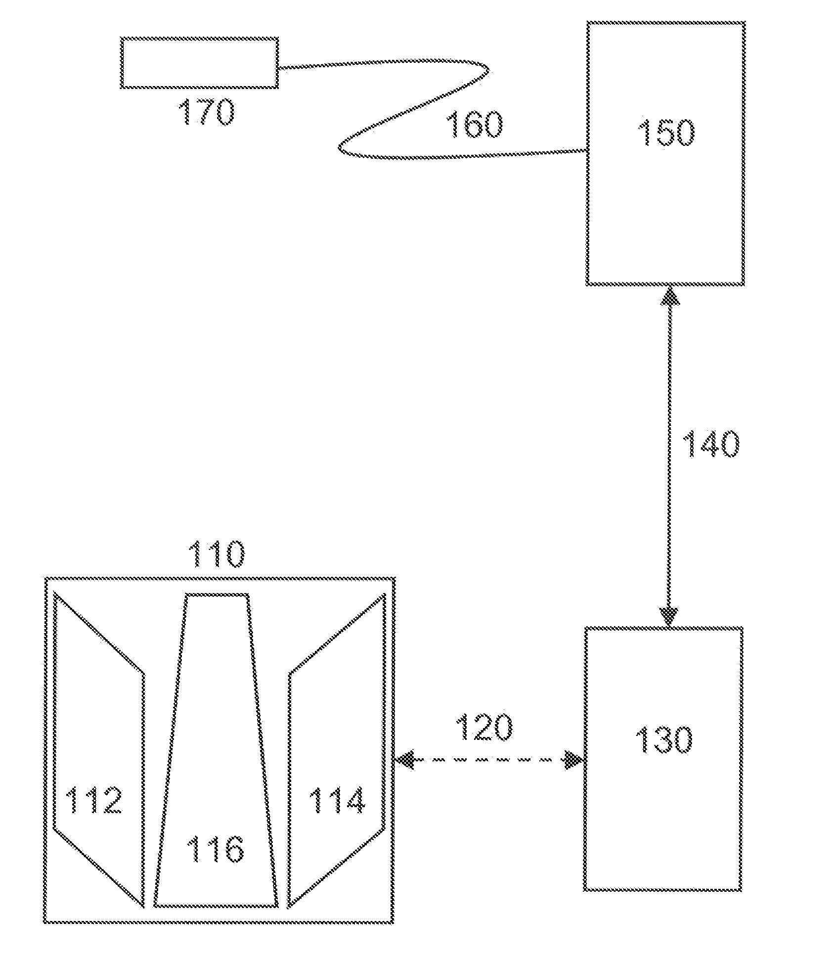
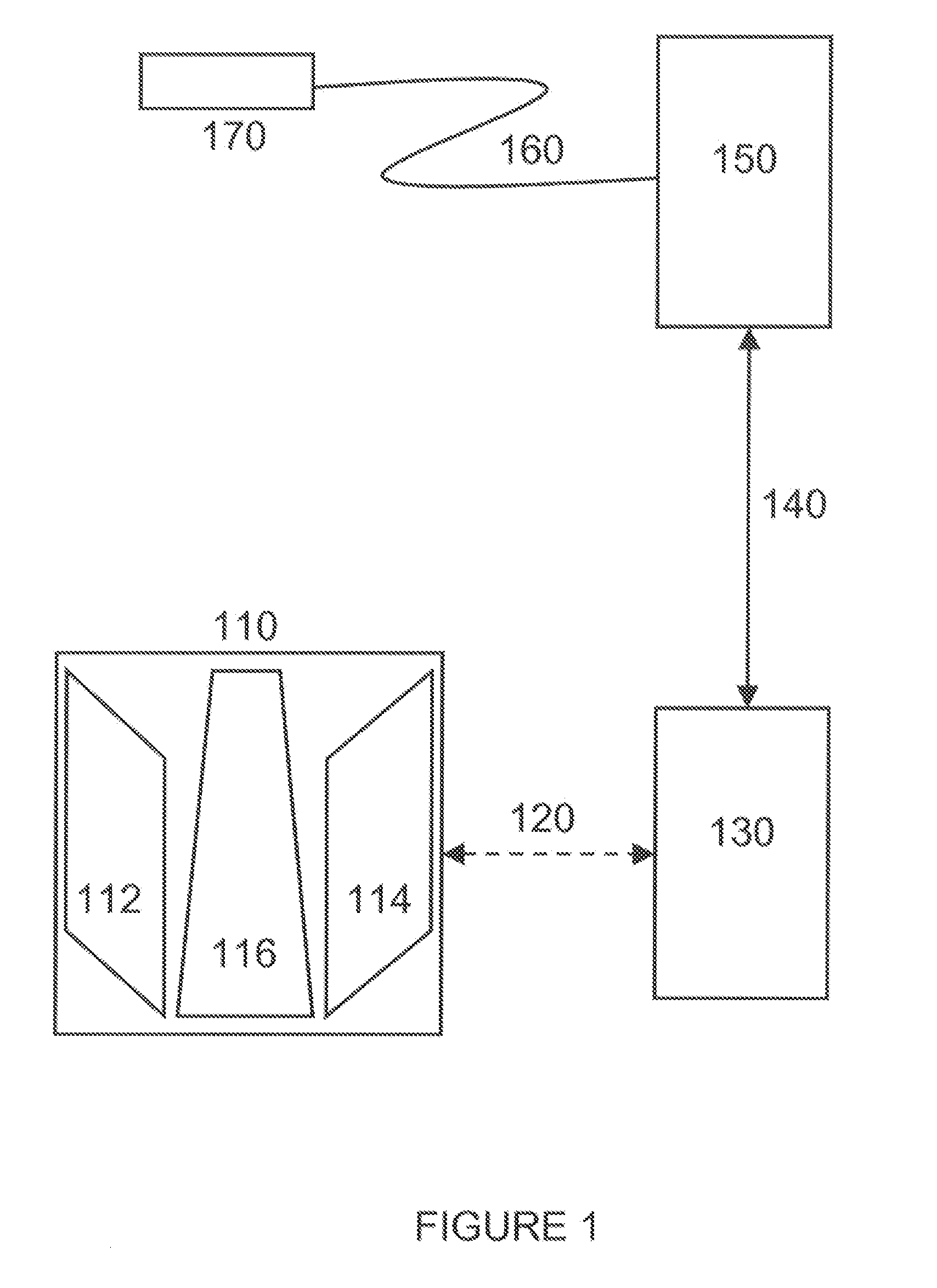
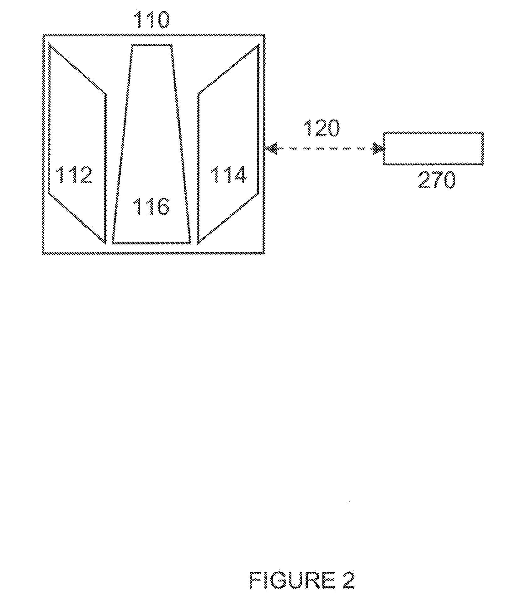
[0008]The invention includes an apparatus for controlling the operation of a surgical device comprising a first wireless transceiver configured to receive a connect signal while in a low power mode and, in response to the connect signal, to transmit low power wireless sync signals, and further configured to receive a wireless sync acknowledgement signal and to place the apparatus into a synced state, and a pedal configured to be operated by a foot of a user and to provide a pedal signal, the first wireless transceiver further configured to generate, when the apparatus is in a synced state, a higher power mode wireless signal in response to the pedal signal, wherein the wireless signal controls the operation of the surgical device. The apparatus may further comprise a sync button, wherein the sync button is configured to provide the connect signal to the first wireless transceiver. The surgical device may comprise a second wireless transceiver and a sync button, wherein the sync button is configured to provide the connect signal to the first wireless transceiver. In addition to or instead of the surgical device comprising a second wireless transceiver, the apparatus may comprise a wireless footswitch adapter comprising a wireless transceiver and sync button, wherein the sync button is configured to provide the connect signal to the wireless transceiver. In embodiments with a wireless footswitch adapter, the apparatus may further comprise an electric console for providing power and wired control signals to the surgical device, wherein the wireless footswitch adapter receives the higher power mode wireless signal in response to the pedal signal and transmits a wired signal representative of the higher power mode wireless signal to the electric console.
[0009]The invention includes a system for wirelessly controlling a surgical instrument comprising a wireless footswitch comprising a first wireless transceiver and a pedal configured to be operated by a foot of a user and to provide a pedal signal in response, wherein the pedal signal is converted to a control signal transmitted by the first wireless transceiver; a surgical instrument or a wireless footswitch adapter with a second wireless transceiver; wherein the first wireless transceiver is configured to transmit sync signals in a lower power mode and, upon syncing between the first and second wireless transceivers, the first wireless transceiver transmits control signals in a higher power mode. The wireless footswitch adapter may be operatively connected to an electric console and transmit control signals to the electric console, wherein a surgical instrument has a wired connection to the electric console for receiving the control signals from the electric console.
[0010]The invention includes a method for controlling a surgical instrument comprising providing a wireless footswitch with a first wireless transceiver, a wireless footswitch adapter with a second wireless transceiver, an electric console operatively connected to the wireless footswitch adapter, the surgical instrument being operatively connected to the electric console; transmitting a sync signal from the wireless footswitch in a lower power sync mode to the wireless footswitch adapter; receiving a pedal signal at the wireless footswitch, wherein the pedal signal is provided by depressing a pedal on the wireless footswitch; processing the pedal signal at the wireless footswitch to generate a control signal; transmitting the control signal wirelessly in a higher power mode to the wireless footswitch adapter; transmitting the control signal from the wireless footswitch adapter to the electric console; processing the control signal at the electric console; and controlling the surgical instrument in accordance with the control signal. The electric console may be operatively connected to a plurality of surgical instruments, and the plurality of surgical instruments may be controllable with said wireless footswitch.
[0011]In another aspect, the invention includes a method for controlling a surgical instrument comprising providing a wireless footswitch comprising a first wireless transceiver and the surgical instrument with a second wireless transceiver; transmitting a sync signal from the wireless footswitch in a lower power sync mode to the second wireless transmitter; receiving a pedal signal at the wireless footswitch, wherein the pedal signal is provided by activating a pedal on the wireless footswitch; processing the pedal signal at the wireless footswitch to generate a control signal; transmitting the control signal wirelessly in a higher power mode to the second wireless transceiver; processing the control signal at the surgical instrument; and controlling the surgical instrument in accordance with the control signal. The wireless footswitch may be synced to a plurality of surgical instruments, and the wireless footswitch may control one of the plurality of surgical instruments synced to the wireless footswitch.
[0012]In each of the embodiments of the invention, the lower power mode may be adjusted to a power that allows syncing the wireless footswitch with a wireless footswitch adapter within a predetermined distance from the wireless footswitch, e.g., in the same room as the wireless footswitch, and does not allow syncing the wireless footswitch with a wireless footswitch adapter beyond the predetermined distance, e.g., outside of the room with the wireless footswitch. The lower power mode may be in the range of about −16.2 dBm and about −7.0 dBm and the higher power mode may be in the range of about −0.7 dBm and about +1.4 dBm. The wireless transceivers in the surgical instrument and / or wireless footswitch adapter may remain in a higher power mode and monitor transmissions from a third wireless transceiver, and wherein when the second wireless transceiver detects a signal from the third wireless transceiver, the second wireless transceiver detects channel and network identification information from the third wireless transceiver, the channel and network identification information being excluded from the possible channels and network identifications available for use when syncing the second wireless transceiver to the first wireless transceiver. The wireless transceivers in the wireless footswitch, the wireless footswitch adapter, and / or the surgical instrument may be IEEE 802.15.4 wireless transceivers using Zigbee network stack communication protocols.

Problems solved by technology

However, many of these applications use wired connections between the controller and the controlled device.
This hardwired arrangement suffers many problems, however, including requiring multiple controllers to control multiple devices, safety hazards from floor to table wiring, and requiring additional effort to maintain a sterile environment.
However, infrared signaling can be problematic because it typically requires the transmitter to be within the line of sight of the receiver or at least requires particular arrangements of the transmitter and receiver that may be inconvenient in practice.
However, these applications frequently suffer from interference from other radiofrequency-emitting devices and thus tend to have problems associating (i.e., bonding or syncing) the controller with a controlled device, particularly where a single controller is used to control multiple devices.
This extra step of physically connecting the device to the controller is inconvenient and may compromise the sterility of a controlled surgical instrument.
However, this approach also suffers from problems associating the controlled device with the controller, and typically requires bringing each controlled device into close proximity to the controller in order to associate (“sync”) the controlled device with the controller.
As with the wired association solution, this approach is inconvenient and may compromise the sterility of a controlled surgical instrument.

Method used


Image

  • Wireless foot controller
  • Wireless foot controller
  • Wireless foot controller

Examples


Embodiment Construction

[0019]The invention includes wireless devices and methods for syncing and communicating between wireless devices. In a preferred embodiment, the invention includes a wireless footswitch device with a wireless transceiver capable of controlling multiple devices each having a wireless transceiver. As used herein, the term “footswitch” includes any controller device operable by foot, including, for example, toggle switches, pushbutton switches, multiple position switches, linear output Hall effect transducer (“Lohet” magnetic to voltage transducer), and potentiometer pedals allowing continuous adjustment of the controller signaling, or any combination of these devices.

[0020]The preferred wireless implementation is the Zigbee standard (IEEE 802.15.4). The wireless footswitch device can beneficially be used in a surgical operating room environment to control surgical or dental devices equipped with wireless transceivers. Examples of surgical devices that can benefit from wireless control...


PUM


Abstract

The invention includes systems and methods for controlling devices including surgical instruments using a wireless footswitch. The systems of the invention include a wireless footswitch, a footswitch adapter, and an electric console for powering and controlling surgical instruments. The systems of the invention further include a wireless footswitch for controlling battery powered surgical instruments. The methods of the invention include syncing a wireless footswitch with a controlled device or a wireless footswitch adapter using a lower power wireless mode, then signaling the controlled device or wireless footswitch adapter using a higher power wireless mode. The systems and methods of the invention include using a wireless device or wireless footswitch adapter to monitor transmissions from other wireless devices to prevent syncing with the wireless footswitch adapter using the same channel or network identification as other wireless devices or wireless footswitch adapters.

Description

BACKGROUND OF THE INVENTION[0001]1. Technical Field[0002]This invention relates to a wireless foot controller that may be used to control devices including medical devices.[0003]2. Description of the Prior Art[0004]Many applications can benefit from hands-free control, and in particular, many surgical applications can benefit by allowing control of surgical instruments without requiring the instruments' operators to use their hands to control the instruments. There have been several applications in the prior art that use footswitches or foot pedals to control surgical instruments. However, many of these applications use wired connections between the controller and the controlled device. This hardwired arrangement suffers many problems, however, including requiring multiple controllers to control multiple devices, safety hazards from floor to table wiring, and requiring additional effort to maintain a sterile environment.[0005]To address these problems, some applications offer wirele...

Claims


Application Information

Patent Timeline
Patent Type & Authority Applications(United States)
IPC IPC(8): A61B17/00
CPCA61B17/32002A61B2017/00221Y02B60/50A61B2017/00973A61B2017/00225G08C17/02Y02D30/70A61B17/00A61B90/08G08C2201/30Y02B70/30
Inventor WARE, MICHAELREINHART, RONALD
Owner LINVATEC
Learn More