Gas shower module

Inactive Publication Date: 2010-05-27
IND TECH RES INST
View PDF23 Cites 7 Cited by
  • Summary
  • Abstract
  • Description
  • Claims
  • Application Information

AI Technical Summary

Problems solved by technology

The use of the aforesaid buffer zone is only suitable for low flow situation, and when it is used in a coating process requiring a high-flow gas, the resulting degree of uniformity is still not satisfactory even though the inflowing gas is distributed by the cooperation of the signal-layered buffer zone and the gas shower module.
As shown in FIG. 3, there will be non-uniform gas concentrations around the center of the substrate 12 which may adversely affect the deposition of the high-flow coating process.
As in the aforesaid gas distribution system, gases will be mixed in the showerhead of the system before they are discharged therefrom so that it is not suitable for discharging gases that are mutually reactive.
Moreover, since the gas distribution network formed inside the aforesaid system is very complex that not only it is difficult but also it can be very expensive to fabricate.
Although the aforesaid method and showerhead are quite capable of delivering gases with satisfactory degree of uniformity, its structure is still very complex and can be very expensive to manufacture.
Despite the aforesaid showerhead is able to prevent gases from mixing and reacting with each other before it is distributed and can deliver the mixed gas with satisfactory degree of uniformity, its structure is still very complex and can be very expensive to manufacture.

Method used


Image

  • Gas shower module
  • Gas shower module
  • Gas shower module

Examples


Embodiment Construction

[0036]For your esteemed members of reviewing committee to further understand and recognize the fulfilled functions and structural characteristics of the invention, several exemplary embodiments cooperating with detailed description are presented as the follows.

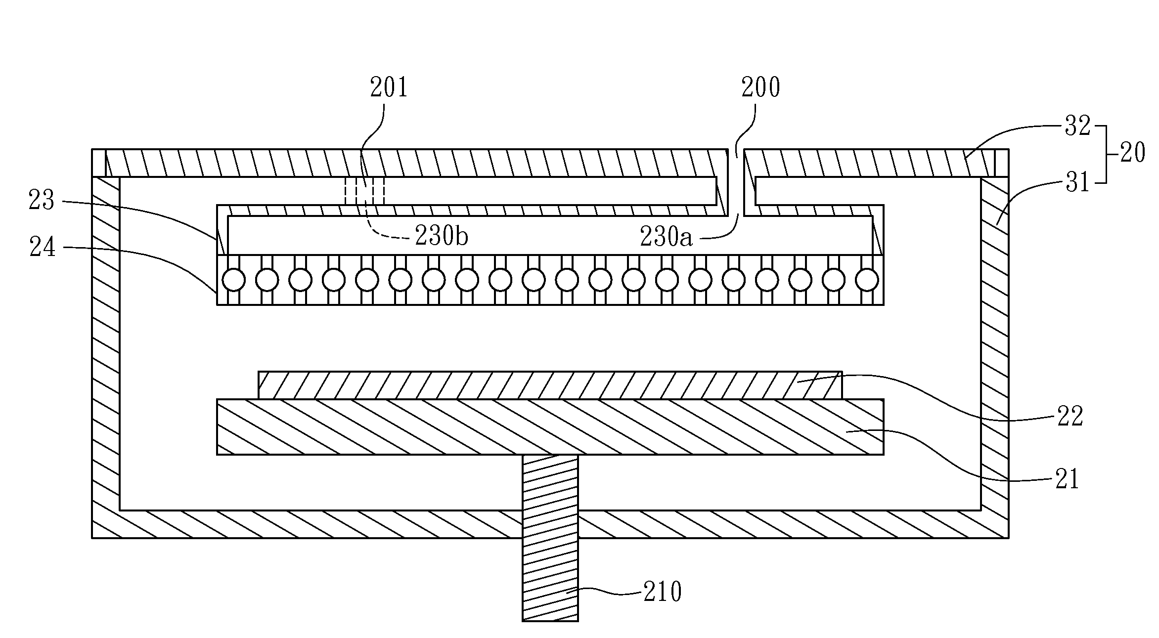
[0037]Please refer to FIG. 5, which is a cross sectional view of a gas shower module for gas deposition chamber according to the present invention. As shown in FIG. 5, there is a carrier 21 disposed in a chamber 20 in a manner that one side of the carrier is provided for carrying a substrate 22 for processing and heating while another side of the carrier 21 is connected to a lifting device 210 for adjusting the height of the carrier 21. The chamber 20 is composed of a rectangular-shaped tank 31 and a cap 32, in which there are a distributor 23 and a shower 24 disposed over the substrate 22 while being connected with each other. The distributor is configured with a first inlet 230a and a second inlet 230b in that the first inle...


PUM

PropertyMeasurementUnit
Diameteraaaaaaaaaa
Diameteraaaaaaaaaa
Circumferenceaaaaaaaaaa

Abstract

A gas shower module for gas deposition chamber with gas channel is disclosed, which comprises: a distributor with at least one diffusion cell positioned therein along first axial direction and a plurality of inlets respectively connecting to the gas channel and the diffusion cell; and a shower with at least one shower channel positioned therein along second axial direction, gas-inlet passages connected to the diffusion cell and the shower channel, and gas-outlet passages connected to the shower channel and gas deposition chamber; wherein the distributor is connected to the shower so that the diffusion cell will be connected to the shower channel through gas-inlet passages and the first axial direction is not be parallel to the second axial direction.

Description

FIELD OF THE INVENTION[0001]The present invention relates to a gas shower module, and more particularly, to a gas shower module for gas deposition chamber.BACKGROUND OF THE INVENTION[0002]With the advance of chemical vapor deposition (CVD) coating technology, the importance of the gas shower module for uniformly delivering a gas into a process region of a CVD deposition chamber is increasing.[0003]Please refer to FIG. 1, which is a schematic view of a conventional gas shower module. In FIG. 1, there is a carrier 11 configured in a chamber 10 that is used for carrying and heating a substrate 12. Accordingly, there is a gas channel 100 formed inside the chamber at a position corresponding to the substrate 12 while enabling the gas channel 100 to be connected to a gas shower module 13. The gas shower module 13 is conventionally formed as a metal panel having a plurality of holes symmetrically distributed thereon, and is designed for enabling a gas that is being fed into the chamber 10 ...

Claims


Application Information

Patent Timeline
IPC IPC(8): C23C16/54
CPCC23C16/45559C23C16/45565C23C16/45561
Inventor CHIANG, MING-TUNGCHIEN, JUNG-CHENHO, JUNG-CHENHUANG, CHIH-YUNG
Owner IND TECH RES INST
Why Eureka
Try Eureka