
Trepanning Drill

a drill and drill bit technology, applied in the field of drill bit, can solve the problems of drill bit production, drill bit axial force, time required for drill disassembly,

Inactive Publication Date: 2010-05-20
ISCAR LTD
View PDF1 Cites 14 Cited by
  • Summary
  • Abstract
  • Description
  • Claims
  • Application Information

AI Technical Summary

Problems solved by technology

When drilling into a composite material, a main drawback is the dust produced in the drilling process.
Another problem that arises when drilling into composite materials is that during the drilling process the drill applies axial forces on the material.
However, a drawback of such a use is the time required for dismantling the drill in order to remove the core produced after each or several drilling processes.

Method used


Image

  • Trepanning Drill
  • Trepanning Drill
  • Trepanning Drill

Examples


Embodiment Construction

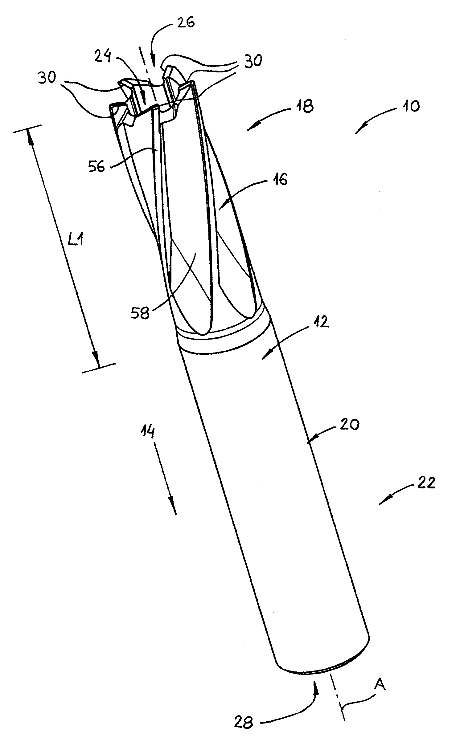
[0033]Attention is drawn to FIGS. 1 to 4 showing a trepanning drill 10 in accordance with the present invention. The trepanning drill 10 comprises a drill body 12 and a drill axis of rotation A defining a front to rear direction 14 of the trepanning drill 10. The drill body 12 comprises a cutting portion 16 of a first length L1, in a front portion 18 of the drill body 12, and a shank portion 20, in a rear portion 22 of the drill body 12. The shank portion 20 may be cylindrical and serves as a holding surface for a machine (not shown) that holds the trepanning drill 10. The trepanning drill 10 may be formed from cemented carbide or other hard metal by any known technique.

[0034]A drill bore 24 extends rearwardly from a front end 26 of the drill body 12 to a rear end 28 of the drill body 12. The present invention is not limited to having a drill bore 24 that extends to the rear end 28 of the drill body 12. In other embodiments, the drill bore may extend only partially along the drill b...


PUM

PropertyMeasurementUnit
axis of rotationaaaaaaaaaa
diameteraaaaaaaaaa
lengthaaaaaaaaaa

Abstract

A trepanning drill having a drill axis of rotation (A) and comprising a drill bore extending rearwardly from a front portion thereof. The drill body has at least two cutting edges formed in the front portion thereof. Each of the cutting edges has a cutting external edge and a cutting internal edge. A circle passing through the cutting external edge of each of the cutting edges forms an external circle having a first diameter (D1) and a first center (A1). A circle passing through the cutting internal edge of each of the cutting edges forms an internal circle having a second diameter (D2) and a second center (A2). In an end view of the trepanning drill, the first center (A1) coincides with the drill axis of rotation (A), and, the second center (A2) is offset from the drill axis of rotation (A).

Description

FIELD OF THE INVENTION[0001]The present invention relates to the field of trepanning drills and more specifically to the field of trepanning drills for drilling into composite materials.BACKGROUND OF THE INVENTION[0002]The use of composite materials has been widely spread these days, especially in the aerospace industry. The composite materials typically comprise of several layers having different structure from one another.[0003]When drilling into a composite material, a main drawback is the dust produced in the drilling process. The negative effects of this dust on the human body are known and, therefore, there is a need to reduce to a minimum the amount of dust produced during a drilling process.[0004]Another problem that arises when drilling into composite materials is that during the drilling process the drill applies axial forces on the material. When drilling a through bore, the axial forces tend to cause delamination of the drilled material in the periphery of the drill bore...

Claims


Application Information

Patent Timeline
Patent Type & Authority Applications(United States)
IPC IPC(8): B23B51/04B23B51/00
CPCB23B51/0406B23B51/0466B23B2226/27Y10T408/9097B23B2265/12Y10T408/78Y10T408/895B23B2251/14B23B51/04
Inventor MEN, DANIEL
Owner ISCAR LTD
Learn More