
Decoder for selectively decoding predetermined data units from a coded bit stream

a data unit and coded bit technology, applied in the field of decoding predetermined data units from a coded bit stream, can solve the problems of inability of decoding, inability to store, and high hardware consumption of conventional decoding devices, so as to save computation resources, computation time and memory, and search for the required information more efficiently.

Active Publication Date: 2010-05-13
ENTROPIC COMM INC
View PDF13 Cites 18 Cited by
  • Summary
  • Abstract
  • Description
  • Claims
  • Application Information

AI Technical Summary

Benefits of technology

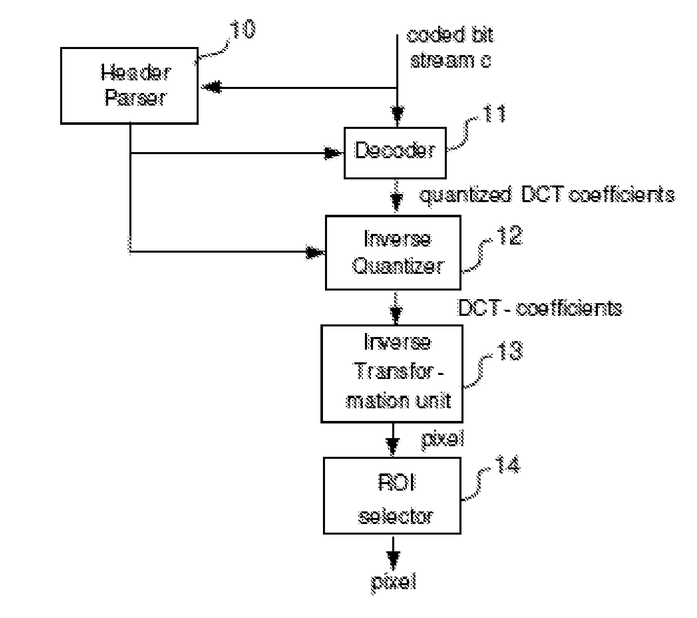
[0029]In detail, the inventive arrangement for decoding at least one predetermined data unit out of a coded bit stream comprises a parsing unit and a decoding unit. The parsing unit searches and collects information about the predetermined data unit in the coded bit stream. The collected information is provided to the decoding unit. The decoding unit decodes the predetermined data unit out of the coded bit stream based on the collected information. The inventive arrangement needs not to decode the coded bit stream completely prior selecting a predetermined data unit included in the coded bit stream. The parsing unit searches and extracts necessary information such that the decoder is able to selectively decode the predetermined data unit out of the coded bit stream. There is no need for large header information in the coded bit stream or to completely decode the coded bit stream prior selecting the predetermined data unit. Therefore, a memory will not be loaded with redundant data and the required computation steps performed by the decoding unit and the parsing unit are reduced. Accordingly, memory and computing resources are saved and the predetermined data unit is decoded with less computing time.
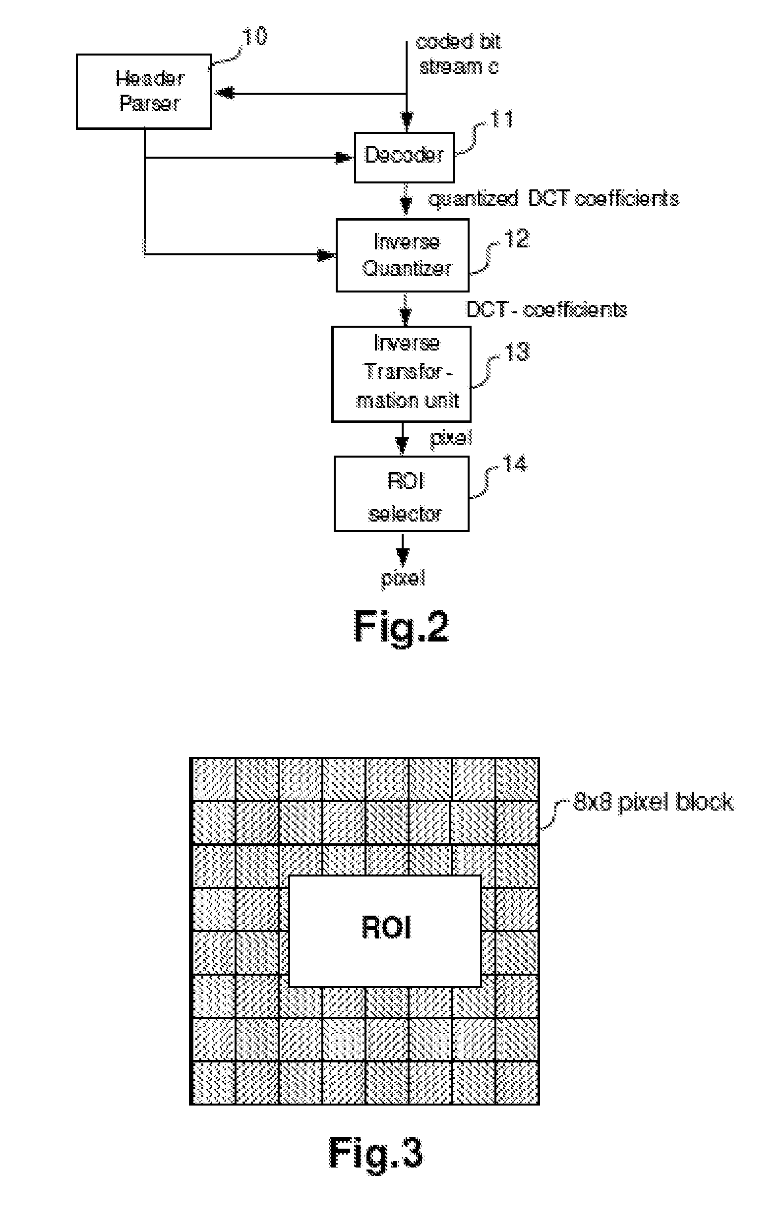
[0041]An apparatus for selectively displaying a ROI of a JPEG compressed picture using the inventive arrangement to decode at least one predetermined data unit out of a coded bit stream comprises the above described arrangement, an inverse quantizer, an inverse transforming unit, and a output unit including e.g. an image buffer and a display. The coded bit stream comprising the JPEG compressed picture is received by the inventive arrangement selectively decoding all quantized DCT-coefficients corresponding to the MCU necessary to reconstruct the 8×8 pixel blocks at least partly including the ROI. Successively, the inverse quantizer multiplies the quantized DCT-coefficients appropriately. Now, the inverse transforming unit transforms all multiplied quantized DCT-coefficients of the MCUs corresponding to the 8×8 pixel blocks at least partly comprising the ROI and reconstructs the 8×8 pixel blocks from the according MCU. Then, the resulting pixels of the 8×8 pixel blocks are stored into the image buffer. Finally, the display reads out all pixels needed for the ROI and displays the according image. The apparatus comprises an image buffer reduced in size in comparison to the prior art. Further, all components in the apparatus need not to reconstruct the complete JPEG-compressed picture such that the single components have to handle less data traffic and to perform less computation steps. This saves computation time and hardware resources of the apparatus to display the ROI.

Problems solved by technology

However, the coded bit stream comprises code sequences of an unequal length such that the conventional decoder is not able to determine the positions of the single data units in the coded bit stream, such that the coded bit stream appears as one single data unit first.
Therefore, the worst case is, that the conventional decoder needs to reconstruct the whole information bit stream, before a designated data unit is determinable.
Thus, all involved components within the conventional decoder has to handle a huge amount of data needing a lot of computation steps to reconstruct only one designated data unit.
That is, the conventional decoder is extremely time and hardware consumptive, in case of decoding only a few data units out of a coded bit stream comprising a plurality of data units.
A further problem could occur, when a data unit is variable in size.
Especially in applications with limited memory resources it is not suitable to store a complete image for selecting only a section of the image.
However, a directory is only reasonable, if the structure of the data units coded in the coded bit stream is manageable in amount and size.
In other words, if the coded bit stream comprises a lot of small data units, the directory gets large, such that in case of entropy encoding, no overall compression is achieved at all.
Even worse, the new stream size might exceed the size of the original uncompressed data.
Moreover, such a directory is not suitable to all coding schemes.
Especially coding schemes used to transmit uncoded data bits as sparse as possible cannot take advantage of a directory, because the directory cannot be encoded.
Especially in mobile communication it is a necessity to select ROIs due to the limited hardware resources of the mobile devices.
In contrary, the display of a mobile device only provides less resolution.
However, this is technically useless, as shown in the following example.

Method used


Image

  • Decoder for selectively decoding predetermined data units from a coded bit stream
  • Decoder for selectively decoding predetermined data units from a coded bit stream
  • Decoder for selectively decoding predetermined data units from a coded bit stream

Examples


second embodiment

[0059]Preferably, the specification unit 110 is connected to the decoding unit 130 to provide the start position us indicating a start point in the Look Up Table 140 where the decoding unit 130 might start with the decoding process for the ROI reconstruction (not illustrated). Therewith, the specification of the start position us gets independent from the coded bit stream c. In a second embodiment, the line based method as shown in FIGS. 8 and 9 the specification unit 110 is additionally connected to the parsing unit 120 to provide the start position of the MCU line within the coded bit stream c. The parsing unit 120 will use this start position to parse the coded bit stream c until it detects the MCU contributing to the ROI. This detected position will then be used by the decoding unit 130 to decode and reconstruct the ROI itself.

[0060]A further preferred embodiment of the decoder 100 comprises a look-up table 140, hereinafter called LUT. The LUT stores the parsed information up an...

first embodiment

[0069]The line anchor point determination unit 124 determines the bit positions u0pi of the first bits of each line at least partly including the ROI. Accordingly, the line DC-block-coefficient determination unit 125 determines the DC-block-coefficients DC0i of the first 8×8 block included in the first MCU of each line at least partly comprising the ROI. The bit positions u0pi of the first bit of each line and the DC-block-coefficient DC0i of each first 8×8 block of each line at least partly comprising the ROI are now stored in the look-up table 126 connected to the DC-block-coefficient determination unit 128 and the anchor point determination unit 127. The differences to the DC-block-coefficient determination unit 122 and the anchor point determination unit 121 of the parsing unit 120 are in detail the usage of the stored bit positions u0pi of each first bit of each line at least partly comprising the ROI and the usage of the DC-block-coefficients DC0i of each MCU included in the ...


PUM


Abstract

A decoder (100) is disclosed, which selectively reconstructs at least one predetermined data unit out of a coded bit stream (c). The decoder (100) includes a parsing unit (120) to search and parse unambiguous information (up) characterizing the at least one predetermined data unit uniquely. Next, the parsing unit (120) provides this parsed information (up) either directly to a decoding unit (130) or to a look-up table (140) such that the decoding unit (130) could reconstruct the predetermined data unit directly out of the coded bit stream (c) based on the parsed information (up) without decoding and reconstructing the coded bit stream (c) completely. Optionally, a specification unit (110) provides an start position (us) of the coded bit stream (c) to the parsing unit (120) used for starting the search. Therewith, data traffic, computation time and memory resources could be saved for decoding and displaying e.g. compressed JPEG pictures.

Description

FIELD OF THE INVENTION[0001]The invention relates to a decoder and a decoding method for selectively decoding at least one predetermined data unit out of a coded bit stream. Further, it relates to an apparatus having a display with a lower resolution than a picture coded in the coded bit stream.BACKGROUND OF THE INVENTION[0002]Coding schemes are well known in the art. Coding schemes are used to transform information into a more efficient structure for several purposes. As for example, compression coding schemes are used to minimize the size of data including the information, whereas transport coding schemes are used to increase the differences in the information. Other important purposes could be to optimize energy, to increase the recognition of the information or to increase the robustness against outer influences.[0003]An information bit stream is assembled out of code sequences. A code sequence is a predetermined alignment of data bits, as the most minimum interpretable informat...

Claims


Application Information

Patent Timeline
Patent Type & Authority Applications(United States)
IPC IPC(8): H04N7/32H04B1/66G06K9/46
CPCH04N19/60H04N19/132H04N19/162H04N19/182H04N19/44H04N19/167H04N19/176H04N19/17
Inventor GOETTING, DETLEF
Owner ENTROPIC COMM INC
Learn More