
Garnish

a technology for garnishes and sashes, applied in the field of garnishes, can solve the problems of increased labor hours, high manufacturing cost, and increased number of man hours involved in garnishing itself, and achieve the effects of preventing the dislocation of the locking portion, extending the distance, and being easy to manufactur

Inactive Publication Date: 2010-05-06
TOYODA GOSEI CO LTD
View PDF10 Cites 9 Cited by
  • Summary
  • Abstract
  • Description
  • Claims
  • Application Information

AI Technical Summary

Benefits of technology

[0009]The invention has been made with a view to solving the problems described above, and an object thereof is to provide a garnish which can be formed simply and easily while reducing the manufacturing manhours and costs, and which can simply be mounted on a mounting base on a vehicle body.

Problems solved by technology

Thus, some labor hours were required for assemblage of the clip into the assembling eye, and the number of man hours involved in manufacturing the garnish itself was increased.
In addition, as to the clip itself, the anchor portion with the fluke portion provided at the distal end thereof had to be formed, which involved much manufacturing cost, and hence, the manufacturing cost of the clip constituted one of main factors which increased the manufacturing cost of the whole garnish.
In addition, in the garnish employing the strap, in addition to locking the clip on the vehicle body, since the strap, which was provided separately from the garnish body, was necessary not only to be connected to the garnish body but also to be connected and fixed to the vehicle body, some labor hours had to be involved not only in manufacturing the garnish itself but also in mounting the garnish on the vehicle body.

Method used


Image

  • Garnish
  • Garnish
  • Garnish

Examples


Embodiment Construction

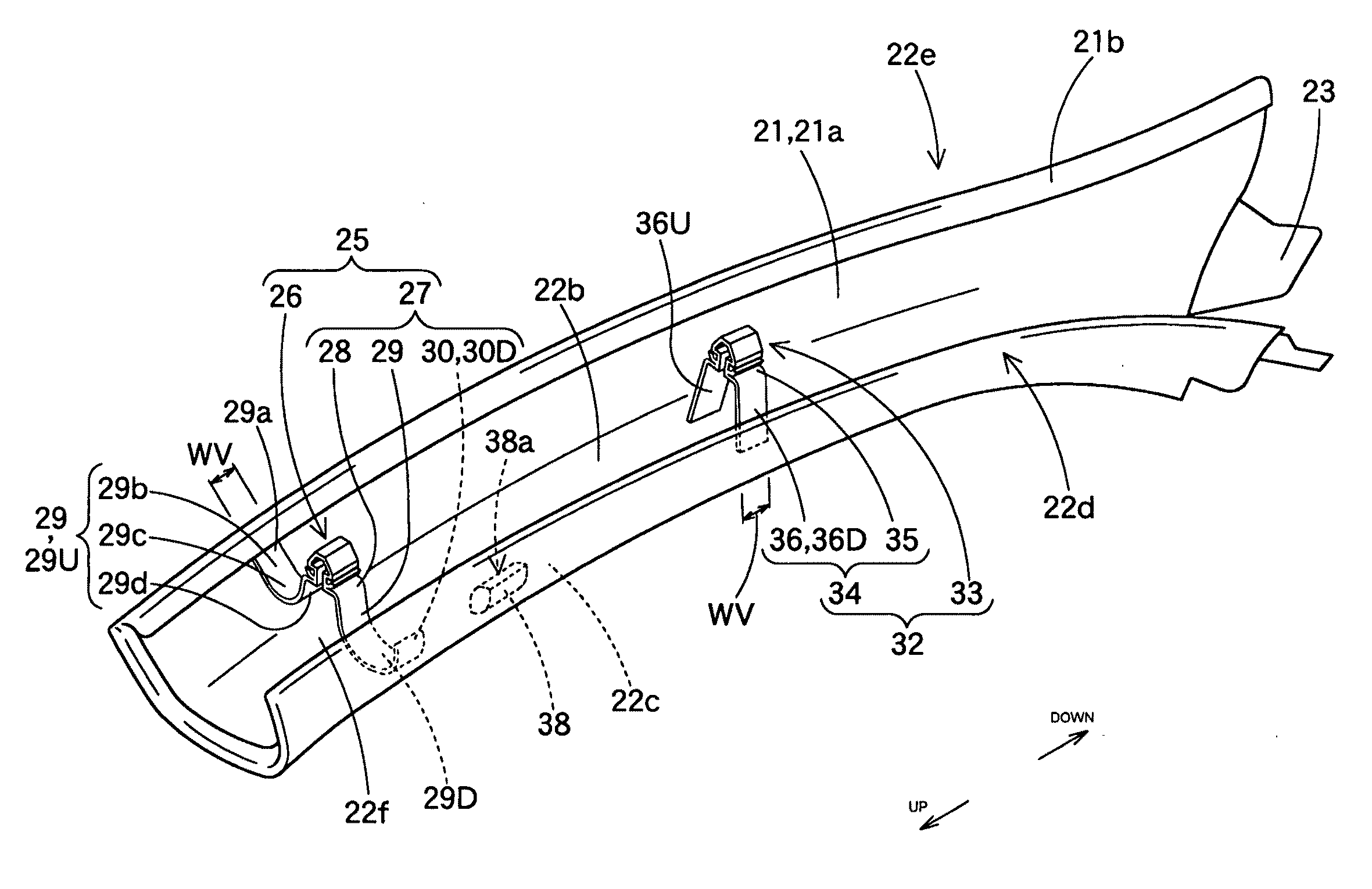
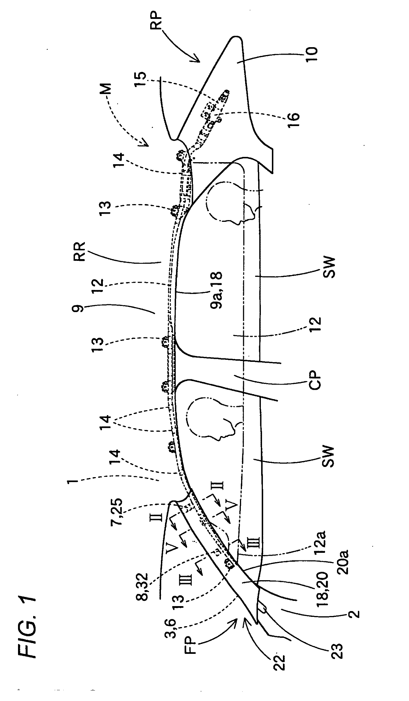
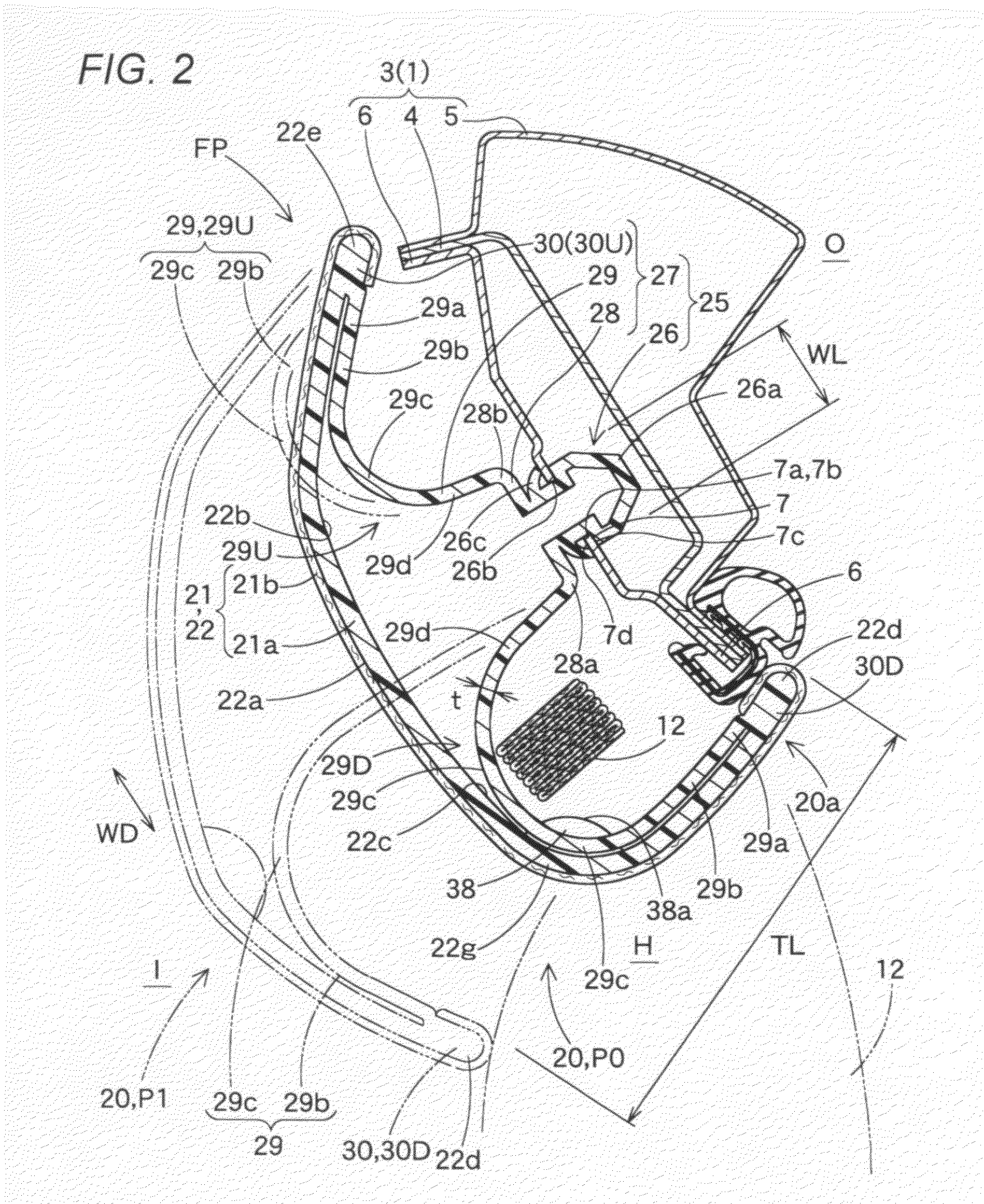
[0034]Hereinafter, an embodiment of the invention will be described based on the drawings. A garnish 20 of an embodiment of the invention shown in FIGS. 1 to 4 is a garnish (a pillar garnish, a front pillar garnish) 20 which is disposed on a side, lying to face a vehicle interior side, of a front pillar portion FP is disposed along substantially a vertical direction of the vehicle. In addition, as is shown in FIG. 1, this garnish 20 is used in a head protection air bag system M in which a folded air bag 12 is disposed so as to extend from a rear pillar portion RP to the front pillar portion FP by way of a roof side rail portion RP, so as to constitute part of an air bag cover 18 which covers the folded air bag 12.

[0035]In addition, in this specification, up-down or vertical directions, left-right or transverse directions or front-rear or longitudinal directions of the garnish 20 and the like are based on a state in which the garnish 20 is installed on a vehicle and coincide with up-...


PUM


Abstract

A garnish includes a garnish body which covers a folded air bag and a locking portion which is inserted to be locked in a mounting hole in a mounting base on a vehicle body. The locking portion holds the garnish body which is pressed by the air bag when the air bag is inflated to move so as to form a projecting space for the air bag.The locking portion includes a locking main body portion which is inserted to be locked in the mounting hole and a connecting piece portion. The connecting piece portion includes a locking base portion on which the locking main body portion is provided, connecting portions which are connected to a rear surface of the garnish body, and deformable portions lying between the locking base portion and the connecting portions and is molded integrally with the garnish body. The deformable portions deform to extend a distance between the locking base portion and the connecting portion when the garnish body moves towards a vehicle interior side.

Description

BACKGROUND OF THE INVENTION[0001]1. Field of the Invention[0002]The present invention relates to a garnish as an air bag cover which is disposed on an inner side of a pillar portion of a vehicle to be pushed to open by an air bag when the air bag is inflated so as to allow the air bag being inflated to project.[0003]2. Related Art[0004]In a conventional head protection air bag system, a garnish which doubled as an air bag cover was disposed on a side of a pillar portion which lies to face a vehicle interior side (for example, refer to JP-A-2006-176089). This garnish was configured so as to include a garnish body and a clip for mounting the garnish body on an inner panel on a vehicle body. The garnish body was disposed to cover a folded air bag, the clip was assembled to an assembling eye provided on a rear surface side of the garnish body, and an assembling hole, which was opened in a rectangular shape for assembling the clip to the assembling eye therethrough, was formed in the ass...

Claims


Application Information

Patent Timeline
Patent Type & Authority Applications(United States)
IPC IPC(8): B60R21/20B60R13/02B60R21/213B60R21/215
CPCB60R13/025B60R13/0275B60R21/213B60R21/215B60R2021/161
Inventor INUI, SHUJIHISHIDA, YUHIGUCHI, YASUYUKIANDO, HIKARU
Owner TOYODA GOSEI CO LTD
Learn More