
System and method for controlling access to video events associated with video broadcast services

Active Publication Date: 2010-04-01
DISH TECH L L C
View PDF12 Cites 27 Cited by
  • Summary
  • Abstract
  • Description
  • Claims
  • Application Information

AI Technical Summary

Benefits of technology

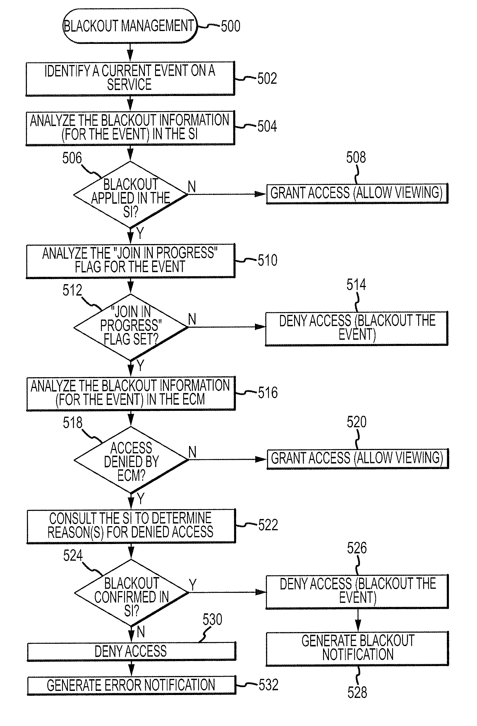
[0008]The techniques and systems described herein alleviate the shortcomings of the prior art by providing a mechanism by which blackout information for video events can be updated and processed with very low latency, relative to conventional methodologies. Quick updating of blackout information at a set-top box of a satellite system is particularly desirable when live back-to-back events are involved.

Problems solved by technology

Conventional satellite systems handle back-to-back sporting events in a manner that can lead to inconsistent behavior (from the customer perspective), and customer confusion.
In other words, the intended blackout rules will only be applied to the first game (resulting in authorized access to the first game by some viewers, and denied access to the first game by other viewers); the blackout rules for the second game will be temporarily disabled or ineffective during the first game.
Otherwise, prescheduled blackout data may cause the first game to be blacked out as of the scheduled start time of the second game.
Moreover, the SI includes a relatively large amount of data (approximately 40 megabytes), which requires lots of time to spool and transmit on a system-wide scale.
In other words, a real-time change to the blackout data (e.g., in response to the end of an overtime game) will not be effective in the set-top box for at least twenty minutes.
The latency associated with the updating of blackout data in the SI, and the traditional approach for handling blackout data can be the source of confusion at the customer end.
This can mislead the customer into believing that he will be able to watch the second game following the first game.

Method used


Image

  • System and method for controlling access to video events associated with video broadcast services
  • System and method for controlling access to video events associated with video broadcast services
  • System and method for controlling access to video events associated with video broadcast services

Examples


Embodiment Construction

[0019]The following detailed description is merely illustrative in nature and is not intended to limit the embodiments of the subject matter or the application and uses of such embodiments. As used herein, the word “exemplary” means “serving as an example, instance, or illustration.” Any implementation described herein as exemplary is not necessarily to be construed as preferred or advantageous over other implementations. Furthermore, there is no intention to be bound by any expressed or implied theory presented in the preceding technical field, background, brief summary or the following detailed description.

[0020]Techniques and technologies may be described herein in terms of functional and / or logical block components, and with reference to symbolic representations of operations, processing tasks, and functions that may be performed by various computing components or devices. Such operations, tasks, and functions are sometimes referred to as being computer-executed, computerized, s...


PUM


Abstract

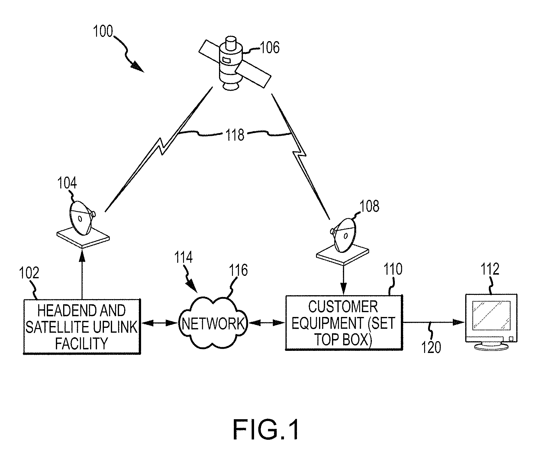
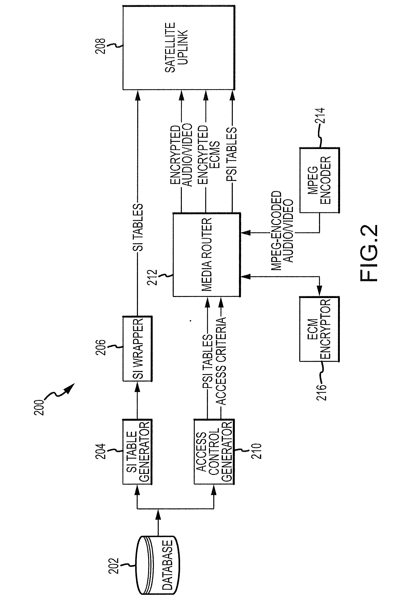
The video services receiver system and related operating methods disclosed herein enable better management of blackout information for events associated with a broadcast service, such as a satellite television service. A system for providing video content to a display for viewing by a customer includes a receiver interface configured to receive data associated with a service, a display interface for the display, at least one memory element configured to store dated blackout information for events on the service, and to store frequently updated blackout information for events on the service, and a processor coupled to the receiver interface, the display interface, and the at least one memory element. The processor is configured to control access to a current event on the service by analyzing both the dated blackout information and the frequently updated blackout information. The processor is configured to present video content associated with the current event if access is granted.

Description

TECHNICAL FIELD[0001]Embodiments of the subject matter described herein relate generally to digital video systems such as satellite video systems. More particularly, embodiments of the subject matter relate to controlling customer access to video events using blackout information associated with the video events.BACKGROUND[0002]Most television viewers now receive their video signals through a content aggregator such as a cable or satellite television provider. In the typical instance, encoded television signals are sent via a cable or wireless data link to the viewer's home, where the signals are ultimately decoded in a set-top box or other consumer device. The decoded signals can then be viewed on a television or other appropriate display as desired by the viewer.[0003]Digital video broadcasting (DVB) systems, such as satellite systems, are generally known. The terms “service” and “event” are often used when referring to video programming delivered via a satellite system. In this c...

Claims


Application Information

Patent Timeline
IPC IPC(8): H04N7/16
CPCH04N7/165H04N21/2541H04N21/25816H04N21/25841H04N21/4516H04N21/6143H04N21/454H04N21/4542H04N21/45455H04N21/45457H04N21/4524
Inventor SWENSON, ERIK
Owner DISH TECH L L C
Learn More