
Device for training athletic or sports ball players

a technology for athletics and sports balls, applied in the field of athletic or sports ball players training devices, can solve the problems of increasing the risk of injury to players, difficult to simulate and practice strategic shots without additional players, and the task of observing which balls hit a particular target becomes even more difficul

Inactive Publication Date: 2010-03-11
HAYES BERNARD
View PDF15 Cites 14 Cited by
  • Summary
  • Abstract
  • Description
  • Claims
  • Application Information

AI Technical Summary

Benefits of technology

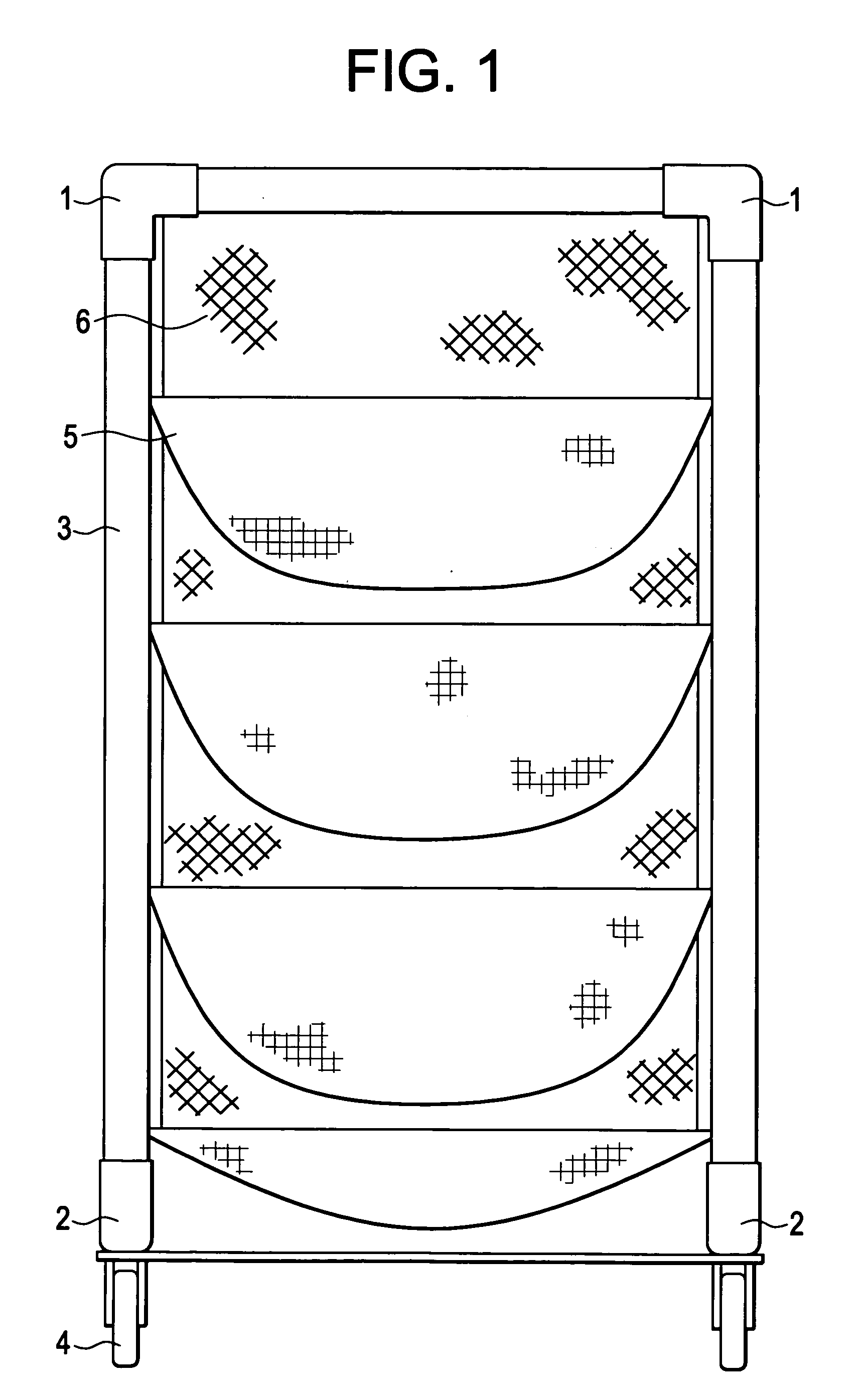
[0013]The present invention provides a device designed to increase the accuracy of one or more of the throwing, batting, bouncing, propelling by stick and kicking of an athletic or sports ball such as a baseball, softball, basketball, football, lacrosse ball or soccer ball. The apparatus is constructed of a scaffolding, frame, or base, for example of aluminum tubing or plastic tubing. A mesh or fabric is attached to, hung over or substantially encases the scaffolding, frame, or base. Further, the mesh or fabric provides a plurality of pouches that may be aligned horizontally at various heights from top to bottom of the device. These pouches provide a target area for the athletic or sports ball. The pouches are optionally designed to allow the ball to drop from a pouch it enters to a second pouch or to the bottom of the device for easy removal. The device may be held by a base having wheels and may be steadied by one or more cross bars running across the bottom of the base.
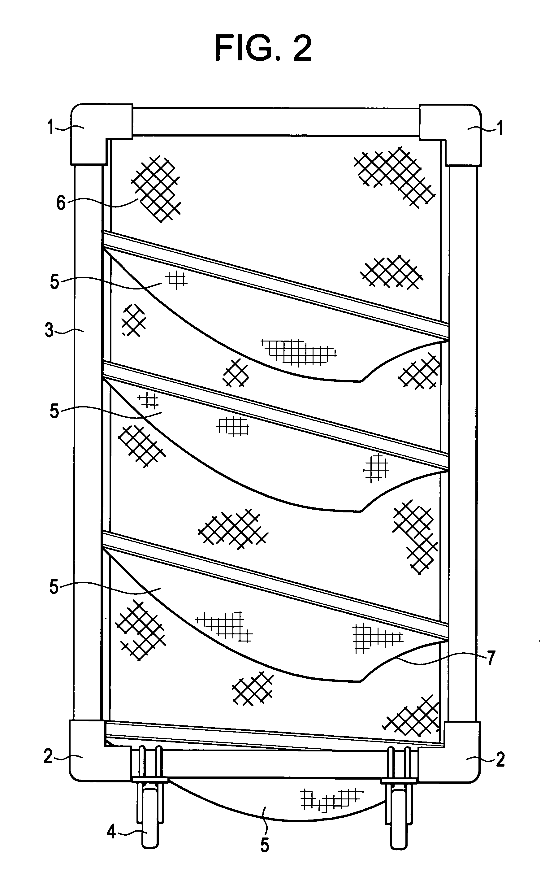
[0016]The device may be useful for training athletes in the games of baseball, soccer, basketball, lacrosse or football. The device may be applicable to practicing throwing, bouncing, batting, propelling by stick or kicking skills. In some embodiments, the pouches are provided with an aperture allowing passage of a ball from one pouch to another. In still further embodiments, the mesh or fabric is provided to form a collection surface or collection pouch at the bottom of the device, underneath the other pouches. The bottom surface therefore provides no aperture to allow a ball to pass to the floor or ground underneath. This feature allows easy collection of a ball after it is thrown, bounced, or kicked into a pouch.

Problems solved by technology

Besides the inconvenience, it is also difficult to simulate and practice strategic shots without additional players.
If multiple players are shooting at the same target, the task of observing which ball hit a particular target becomes even more difficult.
Moreover, the rigid wall increases the risk of injury to a player.
Further, the simulation of real game situations is limited.
U.S. Pat. No. 4,921,257 describes a training device that is limited for use in connection with a conventional soccer goal.
U.S. Pat. No. 5,000,461 describes a complex device which can reposition a single target cup; however, this device is prohibitively expensive to manufacture.
U.S. Pat. No. 6,736,738 describes a football target apparatus, but it is not mounted on wheels, has no rectangular or square base, does not provide a catching assembly constructed of netting and aluminum tubing of about 1.5″ to 2.0″ outside diameter.
Likewise, it provides no assembly that allows a ball to drop to the bottom of the device for easy access and removal.
However, this apparatus is not mounted on wheels having either a rectangular or square base, the frame is rectangular, and is 7-9 feet high.
Likewise, it provides no assembly that allows a ball to drop to the bottom of the device for easy access and removal.
However, this apparatus also is not mounted on wheels having either a rectangular or square base, the frame is rectangular, and is 7-9 feet high.
Likewise, it provides no assembly that allows a ball to drop to the bottom of the device for easy access and removal.
However, it does not describe an apparatus having a base on wheels having either a rectangular or square base.
However, it also does not describe an apparatus having a base on wheels having either a rectangular or square base.
However, it also does not describe an apparatus having a base on wheels having either a rectangular or square base and a rectangular frame from 7-9 feet high.
In addition, it does not describe target areas (pouches) allowing for a ball to drop to the bottom of the device for easy access and removal.

Method used


Image

  • Device for training athletic or sports ball players
  • Device for training athletic or sports ball players
  • Device for training athletic or sports ball players

Examples


Embodiment Construction

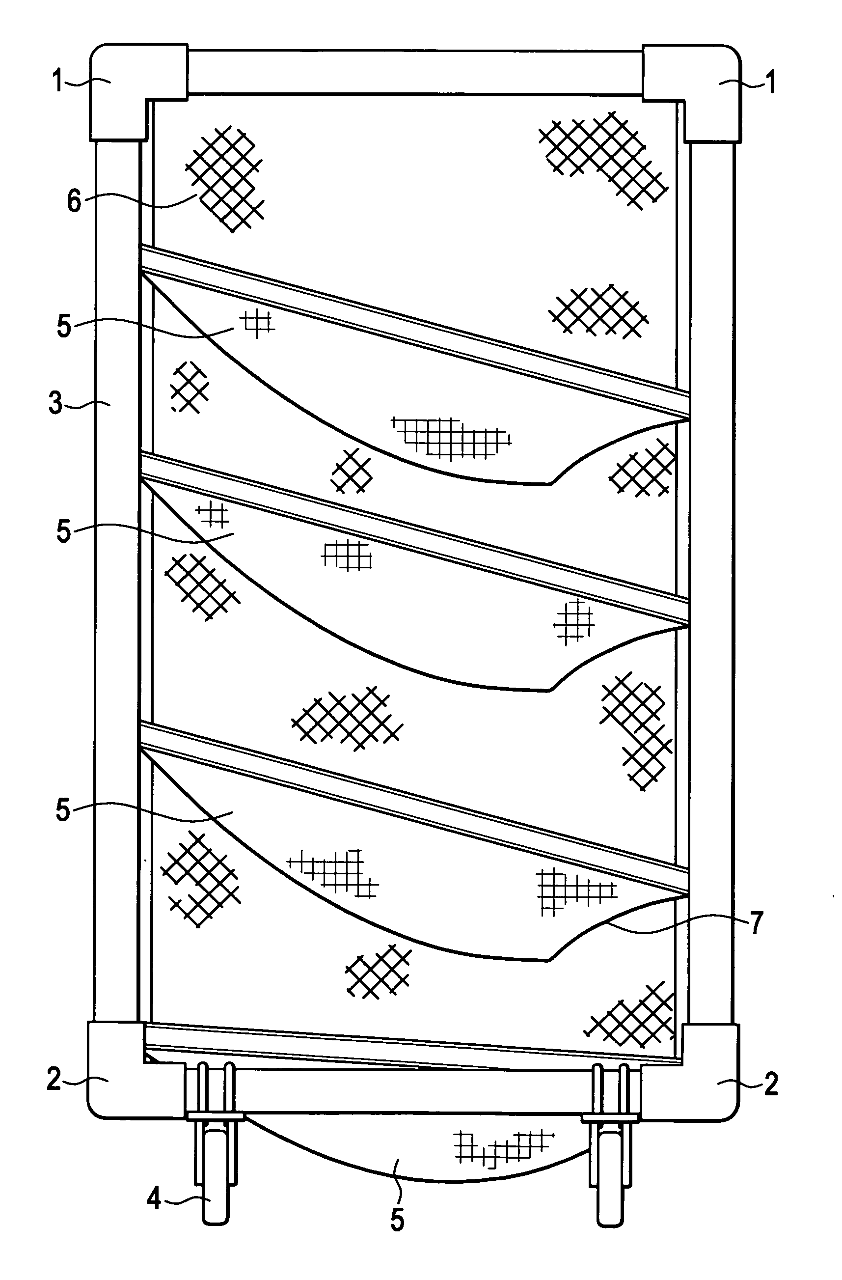
[0023]Some of the preferred embodiments are described with reference to the figures. With reference to FIG. 1, a three way connector 1 mates three members 3 of a frame at three or four positions on the top of the device forming a substantially square or rectangular shape. A two way connector 2 mates two members 3 of a frame at three or four positions on the bottom of the device forming a substantially square or rectangular shape. Thereby a scaffolding, frame or base is formed. Wheels 4 are mounted onto the scaffolding, frame or base to provide a means for easy movement. Pouches 5 are found present in a netting 6 to serve as a target for collecting a ball. The netting may be permanently affixed to the scaffolding, frame or base or temporarily affixed thereto, such as, for instance draped over or encasing the scaffolding, frame or base.

[0024]With reference to FIG. 2, a three way connector 1 mates three members 3 of a frame at three or four positions on the top of the device forming a ...


PUM


Abstract

The present invention provides a device designed to increase the accuracy of both the throwing, bouncing, propelling by stick and kicking of a baseball, football, lacrosse ball or soccer ball. The apparatus is constructed of a frame, for example of aluminum tubing. A net is attached to or hung over the aluminum tubing to provide a series of pouches aligned horizontally at various heights. These pouches provide target areas for a ball. The pouches may be designed to allow the ball to drop from a pouch it enters into a second pouch or to the bottom of the device for easy removal. The device is held by a base that may have wheels and may be steadied by one or more transverse supports running across the bottom or the back of the base.

Description

BACKGROUND OF THE INVENTION[0001]In baseball, it is an object for the pitcher to throw the ball into an area defined as the strike zone, or at least in reasonable proximity thereto. Training aids for pitching practice have been devised to assist would be pitchers to enhance their throwing skill. One such apparatus is shown and described in U.S. Pat. No. 2,978,246 describes a target device including a rectangular generally transparent target plate of a size approximating the strike zone. The target plate is mounted on a pole member having a resilient portion to permit twisting or deflection on impact. U.S. Pat. No. 3,583,703 describes a framework formed of releasable and connectable tubular members, with string members suspended therein to define a strike zone, divided into four generally equally dimensioned parts. U.S. Pat. No. 3,312,467 describes another open framework with strike zone. Another pitching training device is disclosed in U.S. Pat. No. 4,173,337 including a framework s...

Claims


Application Information

Patent Timeline
IPC IPC(8): A63B69/00
CPCA63B63/003A63B2243/0004A63B2243/007A63B2243/005A63B2243/0025A63B2102/14A63B2102/18
Inventor HAYES, BERNARD
Owner HAYES BERNARD
Learn More