Interchangeable toilet tank with urinal

a toilet tank and urinal technology, applied in water installations, lavatory sanitries, constructions, etc., can solve the problems of physical obstruction of the mechanism by a person, difficulty in connecting water and waste drain lines in an existing installation, etc., and achieve the effect of convenient installation

Inactive Publication Date: 2010-02-18
HANSON RICHARD BRIAN +1
View PDF8 Cites 4 Cited by
  • Summary
  • Abstract
  • Description
  • Claims
  • Application Information

AI Technical Summary

Benefits of technology

[0006]The objective of this invention is to provide a urinal function in combination with a toilet that can easily be installed in an existing home or public facility.
[0009]In one configuration, the urinal receptor is mounted to the water closet tank such that it can move over the bowl of the water closet for use. The waste collected in the urinal drops directly into the bowl of the water closet, thus eliminating the requirement for new or additional drain connections. When the toilet is flushed a small amount of water is routed thru a rinse water valve into the urinal to rinse the interior surfaces. This rinse water also drops into the bowl for flushing. When the toilet is to be used for a seated application, the urinal is moved back to a parked position in the tank. The rinse water valve is automatically deactivated to prevent rinse water from entering the urinal when parked. A plug at the discharge of the urinal, automatically engages so that no dripping of residual rinse water can occur when the urinal is not over the bowl.
[0011]The pivot assembly will include a valve that blocks water flow from the toilet flush valve to the urinal when the urinal is not in its full operational position. Thus the urinal when operational, will receive rinse water during the full time the toilet is flushing and refilling the tank. This will insure an effective rinse of the urinal interior surfaces. The valve will close automatically when the urinal is moved to a position where the drain opening is outside the toilet bowl. Thus the possibility of the rinse water flowing when the urinal is not over the bowl is eliminated.

Problems solved by technology

These have major draw backs of how to handle the waste drain line, the odor problem when the toilet is used in a normal seated manner, the physical obstruction of the mechanism when a person is seated and, the difficulty of connecting water and waste drain lines in an existing installation.

Method used


Image

  • Interchangeable toilet tank with urinal
  • Interchangeable toilet tank with urinal
  • Interchangeable toilet tank with urinal

Examples


Embodiment Construction

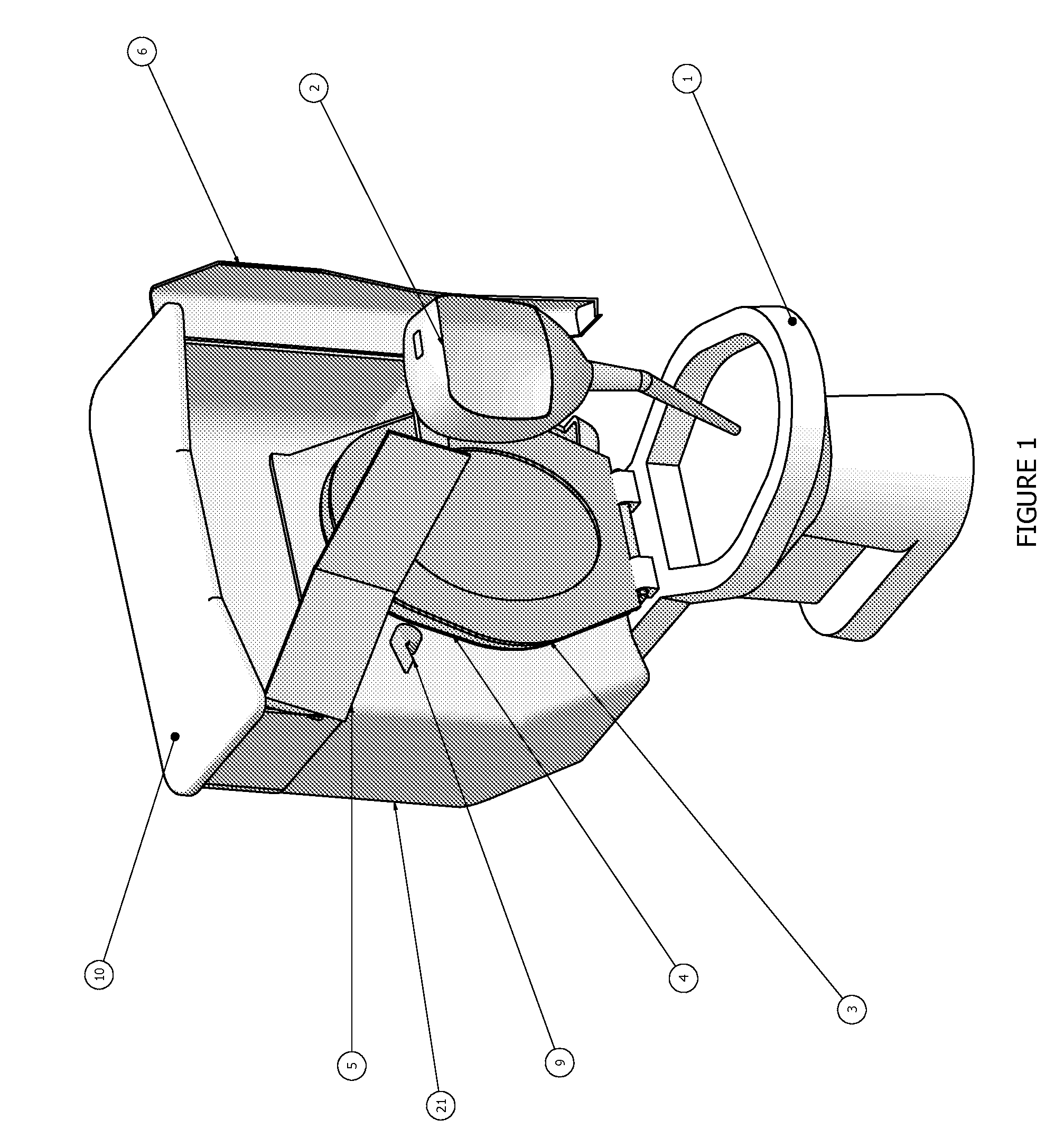
[0022]Referring to FIGS. 1 thru 4, a Toilet Bowl 1 is fitted with standard Seat 3 and Lid 4. The standard Tank is replaced with a special Interchangeable Tank 21 which mounts at the same location on the Toilet Bowl 1 and connects normally to the water supply. The special Tank 21 can be retrofitted to many existing installations without any changes to water supply lines or sewer lines. Alternatively, the special tank features can be an integrated part of a new water closet. Another alternate would be to include the features of this special tank into a water closet of one piece construction.

[0023]The special Tank 21 is taller than standard to accommodate the urinal height required for a standing male. The tank has a Door 6 which swings out with minimum width increase. The Door 6 can be manually moved by the user to allow the Urinal 2 to be moved into the user position over the forward portion of the Toilet Bowl 1. The Door 6 and Urinal 2 can be arranged on either side in alternate emb...


PUM


Abstract

A special toilet tank equipped with a pivoting urinal, to facilitate the collection of urine from a standing male person. This will protect surrounding floors, walls and structure, from urine spray. The folding urinal is moveable from a stored position in the special tank enclosure to a position above the toilet bowl. The urine drops directly into the toilet bowl eliminating the need for a separate drain line. A water line passes through a position valve, to provide rinse water inside the urinal to flush the urine from the inside surfaces. The rinse water also drops into the bowl during flushing. When the urinal is in the stored position, the position valve prevents flow of water to the urinal during normal flushing.

Description

CROSS-REFERENCE TO RELATED APPLICATIONS[0001]Not ApplicableSTATEMENT REGARDING FEDERALLY SPONSORED RESEARCH OR DEVELOPMENT[0002]Not ApplicableREFERENCE TO SEQUENCE LISTING, A TABLE, OR A COMPUTER PROGRAM LISTING COMPACT DISC APPENDIX[0003]Not ApplicableBACKGROUND OF THE INVENTION[0004]The use of a water closet by a standing urinating male has long been recognized as a source of hygienic problems. These problems range from the requirement to raise the seat to avoid contaminating the seating surface for the next user to the destruction of surrounding walls and floors from the attack of the urine. In addition, offensive odor is left by urine on extraneous surfaces.[0005]The need to control the spray of urine on the surrounding surfaces to the toilet has long been recognized in the both the home setting and in public restrooms. Different attempts have been made over time to address these problems. Some of the ideas can be seen in U.S. Pat. Nos. 4,137,579; 4,180,875; 4,282,611; 4,549,321...

Claims


Application Information

Patent Timeline
Patent Type & Authority Applications(United States)
IPC IPC(8): E03D9/06
CPCE03D9/085E03D9/08
Inventor HANSON, RICHARD BRIANHANSON, RICHARD WAYNE
Owner HANSON RICHARD BRIAN
Why Eureka
Try Eureka