
Methods, apparatus, and systems for monitoring transmission systems

a transmission system and transmission system technology, applied in the field of sensing systems, can solve the problems of increasing the cost of repair, and increasing the cost of maintenance and repair, and affecting the operation of the transmission system

Active Publication Date: 2010-02-11
BATTELLE ENERGY ALLIANCE LLC
View PDF74 Cites 44 Cited by
  • Summary
  • Abstract
  • Description
  • Claims
  • Application Information

AI Technical Summary

Benefits of technology

Enables early detection of system damage or anomalies, facilitating preventive measures, minimizing cascading failures, and enhancing security by providing real-time data for operators, while reducing the need for separate power sources and allowing extended monitoring of remote systems.

Problems solved by technology

Transmission systems, such as pipelines, cell towers and electrical power transmission systems, can be damaged in a variety of ways, including damage by weather, by accidents, and by intentional sabotage, just to name a few.
Of course, many elements of such transmission systems are often located in remote areas where monitoring of the systems may be quite difficult, dangerous, and expensive.
However, damage to these transmission systems can result in even more costly and extensive repairs.
For example, damage to multiple towers of an electrical power transmission system could cause cascading or “rolling” blackouts.

Method used


Image

  • Methods, apparatus, and systems for monitoring transmission systems
  • Methods, apparatus, and systems for monitoring transmission systems
  • Methods, apparatus, and systems for monitoring transmission systems

Examples


Embodiment Construction

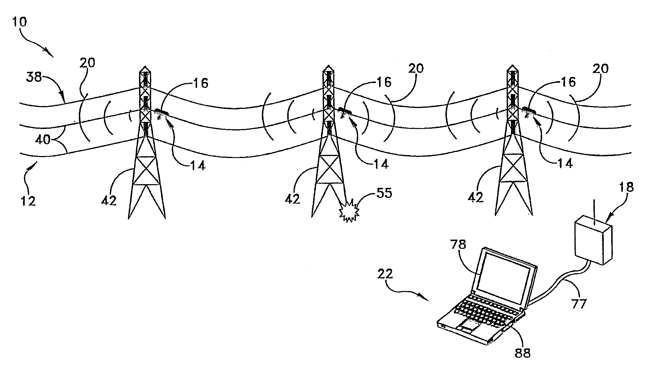
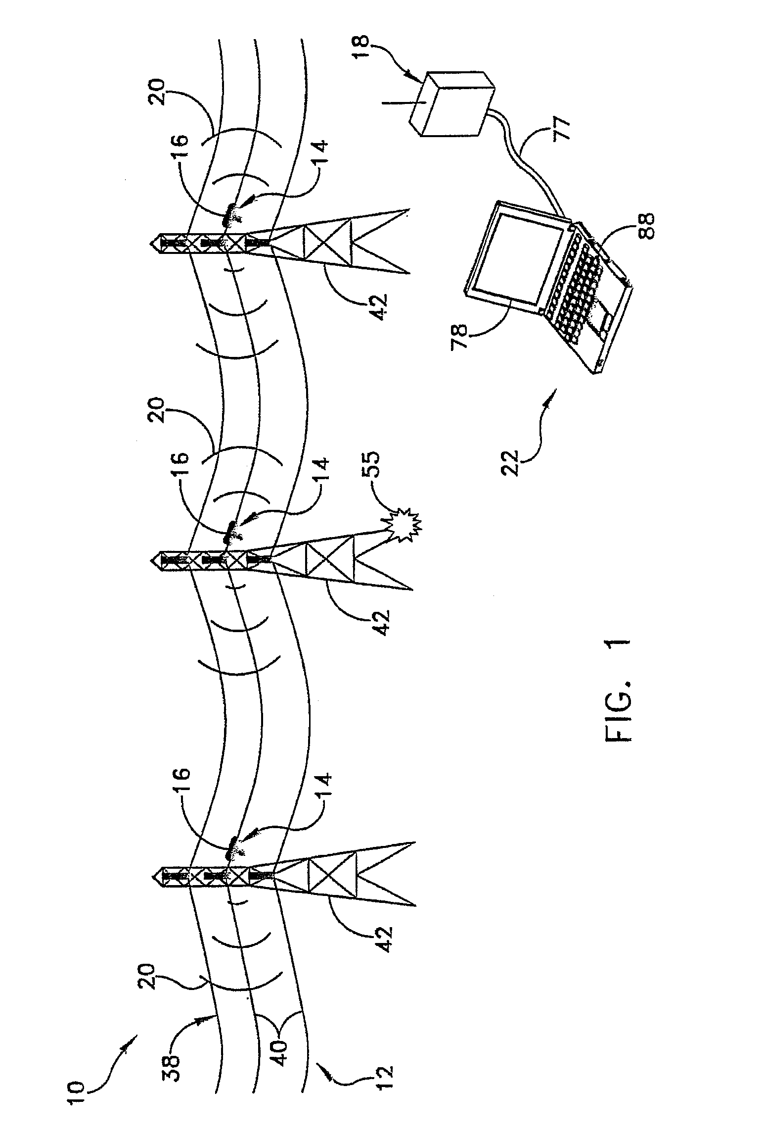
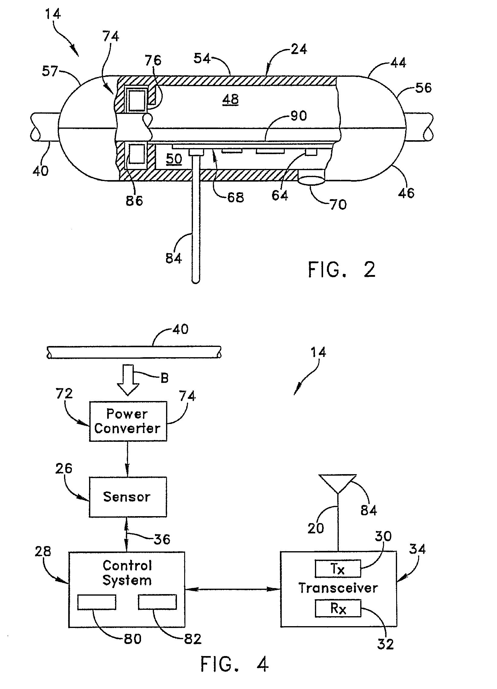
[0016]One embodiment of a monitoring system 10 is shown in FIG. 1 as it may be used to monitor a portion, or even substantially the entirety, of a transmission system 12. By way of example, in one embodiment, the transmission system 12 may comprise an electrical power transmission system 38, although the invention may be used with other types of transmission systems as well. Briefly, the monitoring system 10 may comprise a plurality of individual sensing platforms 14 provided at various locations 16 along the transmission system 12. Monitoring system 10 may also comprise at least one endpoint receiver 18. Endpoint receiver 18 may be positioned so that it receives information 20 transmitted by at least one of the plurality of sensing platforms 14. In the embodiment shown and described herein, endpoint receiver 18 may be operatively associated with a user interface system 22, such as, for example, a personal computer, to allow a user (not shown) to interpret and / or act on the informat...


PUM


Abstract

A sensing platform for monitoring a transmission system, and method therefor, may include a sensor that senses one or more conditions relating to a condition of the transmission system and / or the condition of an environment around the transmission system. A control system operatively associated with the sensor produces output data based on an output signal produced by the sensor. A transmitter operatively associated with the control system transmits the output data from the control system.

Description

CROSS-REFERENCE TO RELATED APPLICATION[0001]This application is a divisional of application Ser. No. 11 / 425,287, filed Jun. 20, 2006, pending. The disclosure of the preceding patent application is incorporated by reference herein in its entirety.CONTRACTURAL ORIGIN OF THE INVENTION [0002]This invention was made with government support under Contract Number DE-AC07-05ID14517 awarded by the United States Department of Energy. The government has certain rights in the invention.TECHNICAL FIELD[0003]This invention relates to sensing systems in general and more specifically to methods, apparatus, and systems for monitoring transmission systems.BACKGROUND[0004]Transmission systems, such as pipelines, cell towers and electrical power transmission systems, can be damaged in a variety of ways, including damage by weather, by accidents, and by intentional sabotage, just to name a few. Of course, many elements of such transmission systems are often located in remote areas where monitoring of th...

Claims


Application Information

Patent Timeline
Patent Type & Authority Applications(United States)
IPC IPC(8): G08C19/16
CPCH04L12/66H04Q9/00H04Q2209/86H04Q2209/88
Inventor POLK, ROBERT E.SVOBODA, JOHN M.WEST, PHILLIP B.HEATH, GAIL L.SCOTT, CLARK L.
Owner BATTELLE ENERGY ALLIANCE LLC
Learn More