
Engine intake passage structure of front vehicle body

a technology of engine intake and intake passage, which is applied in the direction of machines/engines, combustion-air/fuel-air treatment, and bumpers, etc., can solve the problem that the air introduction toward the heat exchanger may not be prevented, and achieve the effect of reducing the risk of water coming

Inactive Publication Date: 2010-02-11
MAZDA MOTOR CORP
View PDF28 Cites 26 Cited by
  • Summary
  • Abstract
  • Description
  • Claims
  • Application Information

AI Technical Summary

Benefits of technology

[0006]Accordingly, an object of the present invention is to provide an engine intake passage structure of a front vehicle body which can properly reduce a risk of the water coming into the inlet of the intake passage of the engine even when the vehicle travels on the flooded road.
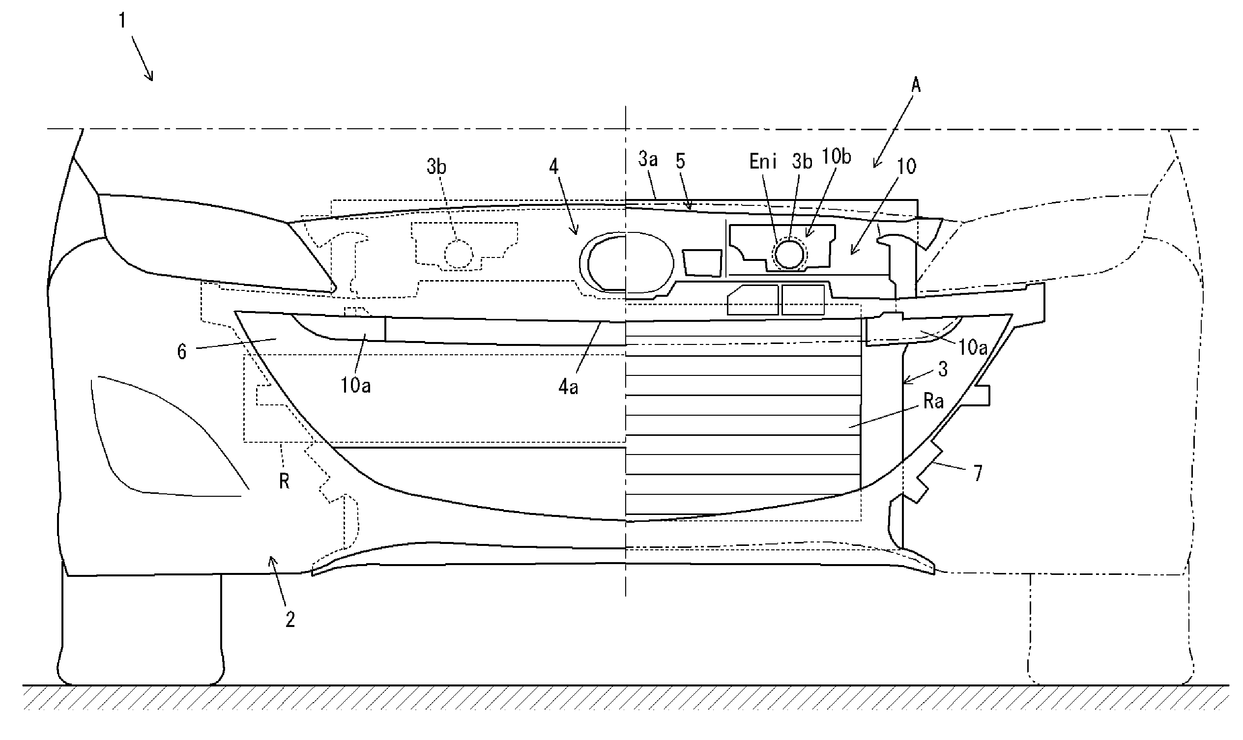
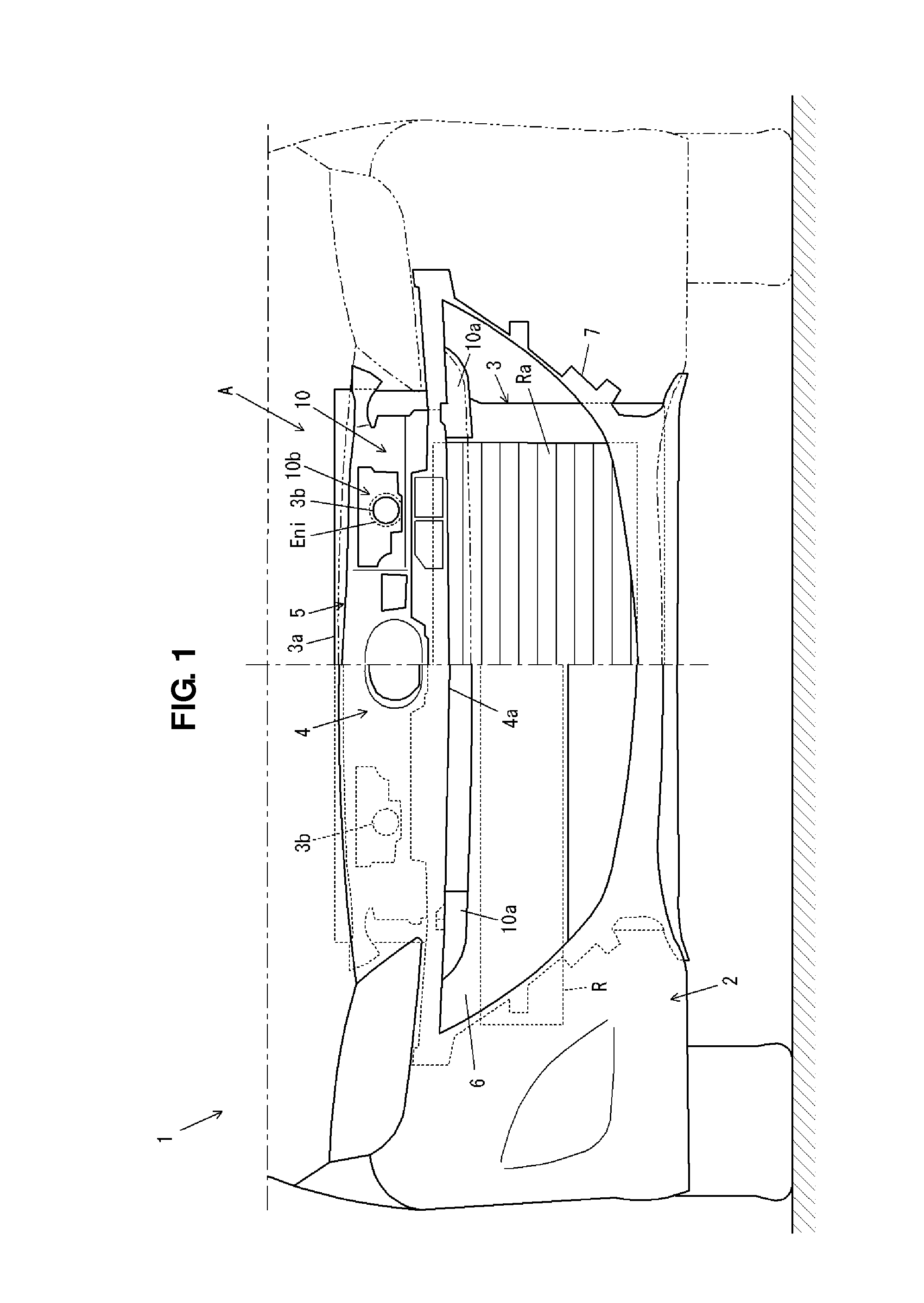
[0008]According to the present invention, part of the air coming in through the air intake opening at the bumper fascia is guided to the inlet of the intake passage of the engine via the duct which has the inlet portion which is disposed so as to be exposed to the upper-side portion of the air intake opening and the outlet portion which connects to the inlet of the intake passage of the engine. Thereby, even if the water coming in the vehicle front body through the air intake opening rises up to the height of the inlet of the engine intake passage in the space behind the inlet portion of the duct and before the heat exchanger, the water can be prevented from coming into the duct as long as the water height on the flooded road is lower than that of the inlet portion of the duct. Thus, the risk of the water coming into the inlet of the intake passage of the engine, which may cause some damage to the engine, can be reduced properly.
[0009]According to an embodiment of the present invention, the air intake opening is formed so as to extend outward in a vehicle width direction beyond the heat exchanger in an elevation view of a vehicle, and the inlet portion of the duct is disposed so as to be exposed to a portion of the air intake opening which is positioned outside of the heat exchanger. Thereby, the inlet portion of the duct does not exist in front of the heat exchanger. Accordingly, even if the inlet portion of the duct is disposed so as to be exposed to the air intake opening, the air introduction toward the heat exchanger may not be prevented.
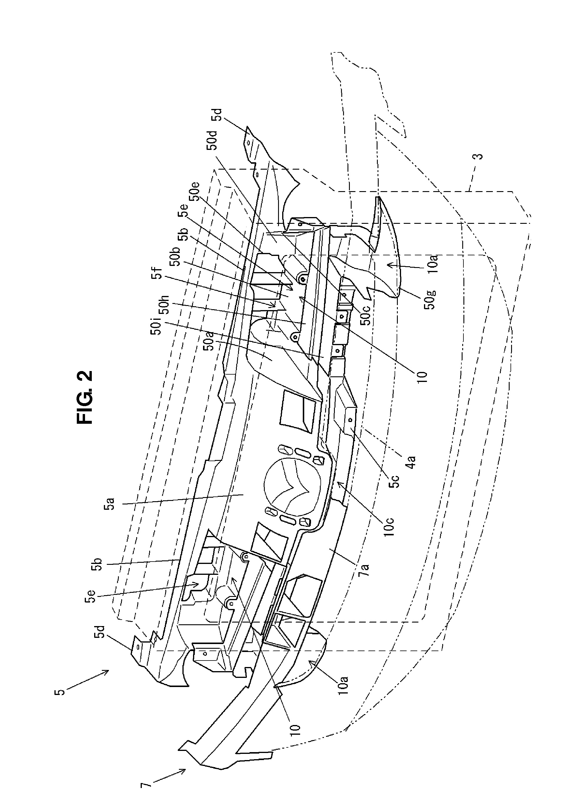
[0011]Thus, according to another embodiment of the present invention, the inlet portion of the duct comprises a plurality of inlets which are disposed away from each other in a vehicle width direction, and there is provided a connection portion which connects downstream portions of the plural inlets and extends in the vehicle width direction at a positioned which is above the inlets of the duct and below the inlet of the intake passage of the engine. Thereby, an enlarged space is ensured by the connection portion of the duct which extends in the vehicle width direction at a middle level between the inlet portion of the duct and the inlet of the engine intake passage. Accordingly, even in case the water comes in through the inlet portion of the duct, the duct can be properly prevented from being filled with the water. As a result, the water coming into the duct can be prevented properly from reaching the inlet of the engine intake passage, and the proper air flow to the inlet of the engine can be ensured. Moreover, since the plural inlets of the duct are provided, even when the water comes in through one of the inlets, the necessary amount of air for the engine can be effectively ensured.
[0012]According to another embodiment of the present invention, a drain portion is provided at the connection portion of the duct. Thereby, the water coming into the duct through the inlet portion is discharged from the drain portion. Accordingly, preventing the water from reaching the inlet of the engine intake duct can be improved.
[0013]According to another embodiment of the present invention, the duct includes the bumper fascia and a member which is provided so as to face to a back face of the bumper fascia. Thereby, since the duct includes the bumper fascia, the duct can be formed properly by using a member which is generally provided at the automotive vehicle. Further, since the duct includes the member which is provided so as to face to the back face of the bumper fascia, the duct can be provided along with the bumper fascia having its increased rigidity.

Problems solved by technology

Accordingly, even if the inlet portion of the duct is disposed so as to be exposed to the air intake opening, the air introduction toward the heat exchanger may not be prevented.

Method used


Image

  • Engine intake passage structure of front vehicle body
  • Engine intake passage structure of front vehicle body
  • Engine intake passage structure of front vehicle body

Examples


embodiment 1

[0031]As shown in FIG. 1, a bumper 2 is provided at a front end portion of an automotive vehicle 1 according to the present embodiment. An engine room where an engine is disposed is provided behind a bumper 2, and a radiator Ra to cool a cooling water of the engine is provided at a front portion of the engine room. The radiator Ra is fixed to a vehicle body via a rectangular shroud member 3. An inlet Eni of an intake passage En of the engine is provided above and in back of the radiator Ra.

[0032]The bumper 2 comprises a bumper fascia 4 which forms a design face of the front end portion of the vehicle body and a bumper-fascia support member 5 which is provided so as to face to a back face of the bumper fascia 4 and attached to an upper portion 3a of the shroud member 3 to support the bumper fascia 4 from behind.

[0033]An air intake opening 4a which introduces outside air therein is formed at a specified portion of the bumper fascia 4 which faces to the heat exchanger Ra. The air intak...

embodiment 2

[0071]According to a second embodiment, as shown in FIG. 12, a duct 110 is made of a particular member which interconnects an upper-portion side of an opening 104a of a bumper fascia 104 and an opening portion 103b of an upper side portion 103a of a shroud member 103.

[0072]The duct 110 has, as shown in FIG. 13 as well, fixing piece portions 110c, 110c, 110d, 110e, 110e to a back face of the bumper fascia 104 at its front end portion and middle portion. The fixing piece portions 110c, 110c of the upper front end of the duct 110 are fixed to a boss 104b which is formed at a back face of an upper edge portion of the opening 104a of the bumper fascia 104 with screws. The fixing piece portion 110d of the lower front end of the duct 110 is fixed to a boss 106a which is formed at a back face of an upper edge portion of the grill member 106 with screws. The fixing piece portions 110e, 110e of the middle portion of the duct 110 are fixed to a boss 104c which is formed at a back face of a spe...


PUM


Abstract

There is provided a duct, an inlet portion of which is disposed so as to be exposed to an upper-side portion of an air intake opening and an outlet portion of which connects to an inlet of an intake passage of an engine. There can be provided an engine intake passage structure of a front vehicle body which can properly reduce a risk of the water coming into the inlet of the intake passage of the engine even when the vehicle travels on the flooded road.

Description

BACKGROUND OF THE INVENTION[0001]The present invention relates to an engine intake passage structure of a front vehicle body in which outside air introduced through an air intake opening formed at a bumper fascia is guided to an inlet portion of an intake passage of an engine which is disposed above a heat exchanger.[0002]In general, a heat exchanger (radiator) to cool a cooling water of an engine is disposed at a front portion of a vehicle body of an automotive vehicle. Further, an air intake opening to introduce outside air for cooling the heat exchanger therein is formed at a specified portion of a bumper fascia which forms an outer face of the front portion of the vehicle body, the specified portion facing to the heat exchanger.[0003]Herein, there may be a case in which the inlet portion of the intake passage of the engine is disposed above the heat exchanger, and part of the outside air introduced through the air intake opening is guided to the inlet portion of the engine intak...

Claims


Application Information

Patent Timeline
Patent Type & Authority Applications(United States)
IPC IPC(8): B60K13/02F02G5/00
CPCF02M35/02F02M35/161F02M35/10013
Inventor OHIRA, TAKAHIDEGONO, SEIJIYOSHIMURA, DAIURATA, YUKARI
Owner MAZDA MOTOR CORP
Learn More