
Hypocycloid Engine

a technology of cycloid engine and assembly, which is applied in the direction of machines/engines, belts/chains/gearings, and belts/chains/gearings, etc., can solve the problems of increasing the friction between the piston, increasing the amount of piston side load, and affecting the engine balance, so as to reduce vibration and increase the efficiency of the engine, eliminate the canting of the connecting rod, and eliminate the piston side load

Inactive Publication Date: 2010-02-11
WISEMAN TECH
View PDF16 Cites 10 Cited by
  • Summary
  • Abstract
  • Description
  • Claims
  • Application Information

AI Technical Summary

Benefits of technology

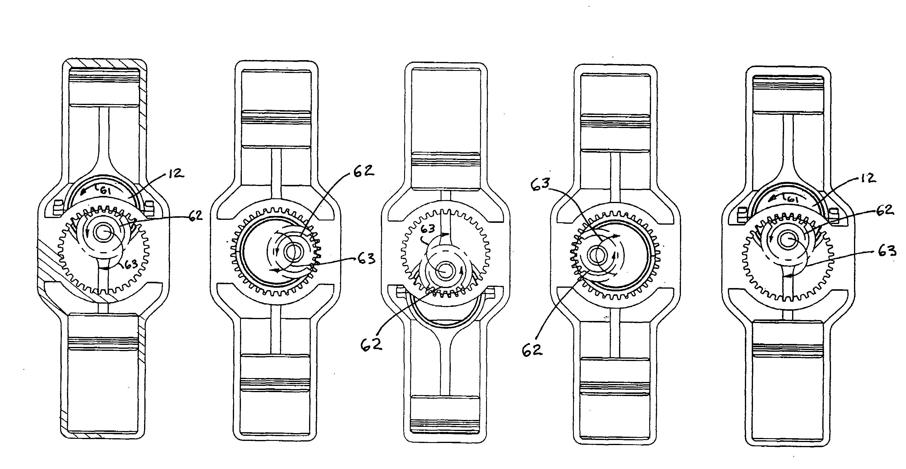
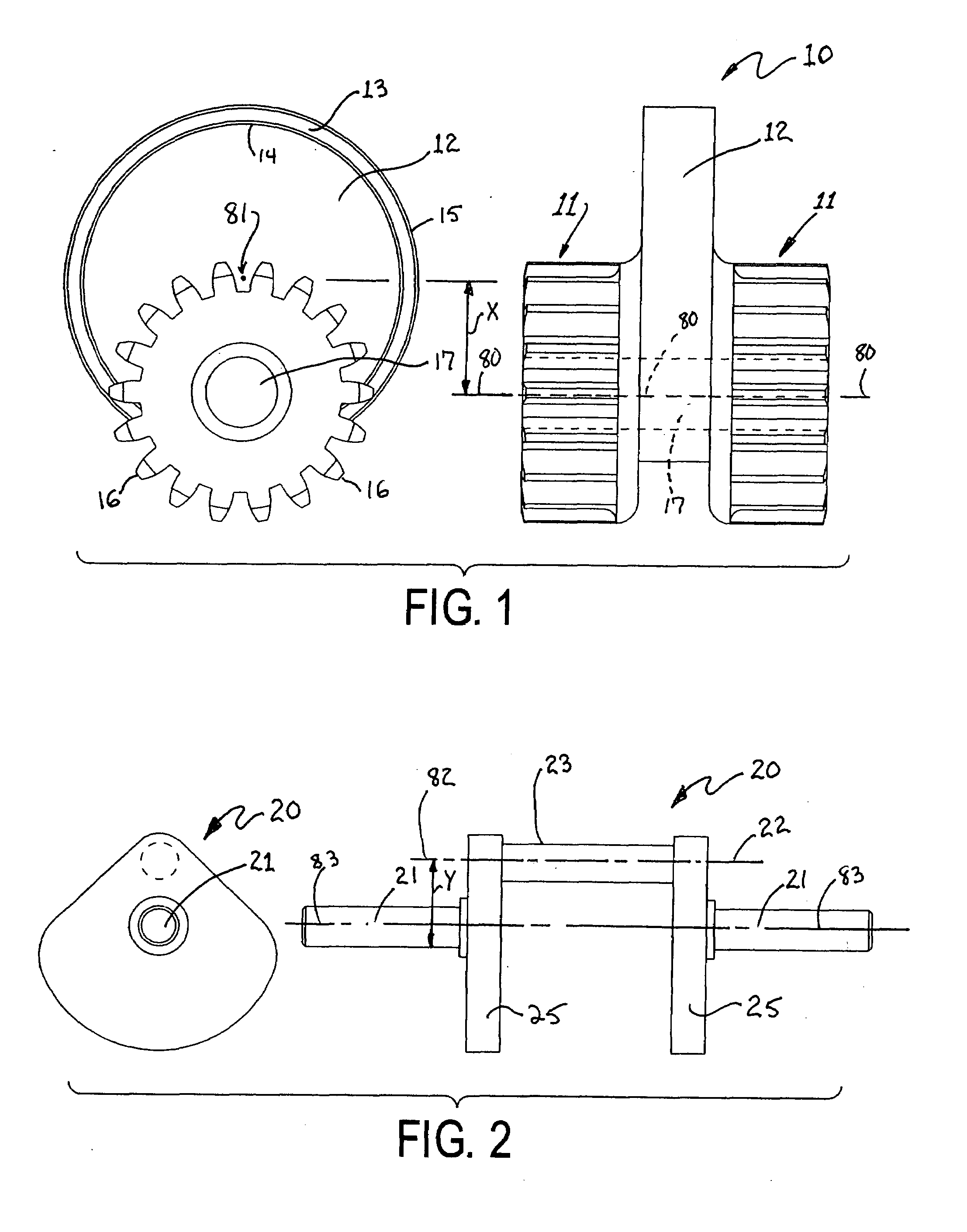
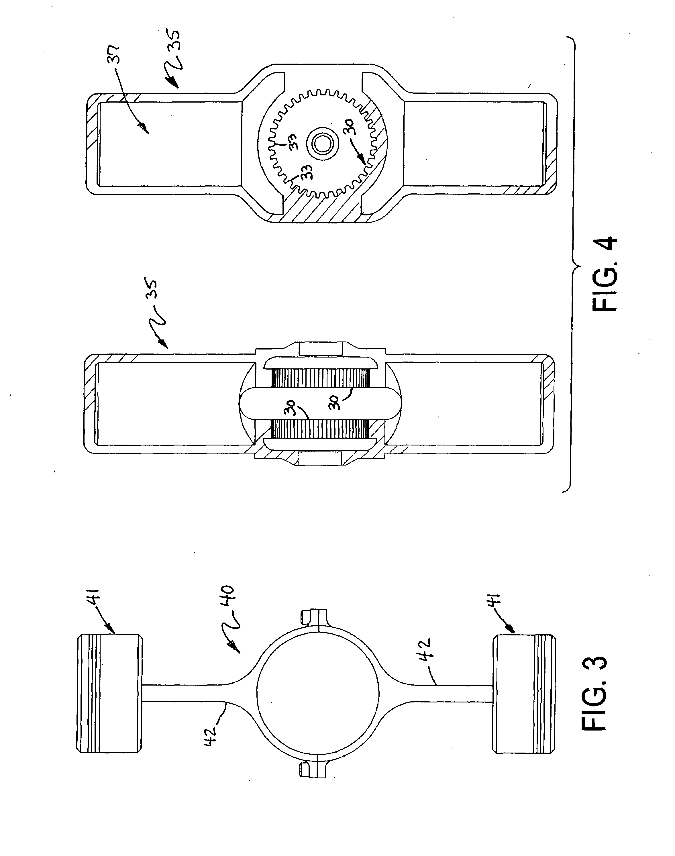
[0010]The hypocycloid engine pinion assembly of the present invention improves on the prior art by providing a simple and efficient means of converting linear motion to rotational motion. The gear mechanism performs this conversion using only two moving parts {other than any piston(s) and associated connecting rod(s)}, the pinion and the drive shaft. The reduction of the number of pieces in the gear assembly to two moving parts makes it easier to manufacture and assemble and reduces the amount of friction generated between the moving parts.
[0012]The invention provides a means to eliminate the canting in the connecting rod so as to eliminate piston side loading and increase the efficiency of the engine.
[0013]The invention provides a means to direct all the energy of the piston into the connecting rod and eliminate any energy loss in a lateral direction to the connecting rod.

Problems solved by technology

The canting also produces piston side loading which increases the amount of friction between the piston and the walls of a cylinder holding the piston.
Furthermore, the rotation of the connecting rod at the gear assembly makes it more difficult to eliminate vibrational effects and balance the engine.
However, many hypocycloid gearing mechanisms in the prior art are extremely complicated, having multiple gears and counterweights.
Furthermore, it is also disclosed that there are several disadvantages to this configuration relating to gear overloading, possible configurations and unsatisfactory lubrication.

Method used


Image

  • Hypocycloid Engine
  • Hypocycloid Engine
  • Hypocycloid Engine

Examples


Embodiment Construction

[0025]As described above, In the background of U.S. Pat. No. 4,237,741 it is disclosed that certain hypocycloids operate in a manner where an externally-toothed gear wheel rolls on or meshes with the gear rim of an inwardly-toothed gear wheel, where the diameter of the inwardly-toothed gear wheel is in the ratio of 2:1 to the externally-toothed gear wheel. Furthermore, it is also disclosed that there are several disadvantages to this configuration relating to gear overloading, possible configurations and unsatisfactory lubrication.

[0026]In contrast to these statements in U.S. Pat. No. 4,237,741, Applicant has unexpectedly discovered that gear overloading and undue gear stress does not occur in the hypocycloid engine assembly of the present invention. Specifically, in an internal combustion engine application, both at top dead center “TDC” and bottom dead center “BDC” the pinion gear and ring gear have zero torque as all the force vectors are aligned in a direction parallel to the ce...


PUM


Abstract

The present invention relates to a hypocycloid engine assembly which may be used in internal combustion engines. The engine assembly is able to transfer power from a purely linear reciprocating piston to a purely rotational output shaft, increasing the efficiency and stability of the gear assembly and engine. The engine assembly may also be used in applications converting purely rotational motion to purely linear motion, for example, in air compressors or hydraulic systems.

Description

FIELD OF INVENTION[0001]The present invention relates to a hypocycloid engine assembly which may be used in internal combustion engines. The engine assembly is able to transfer power from a purely linear reciprocating piston to a purely rotational output shaft, increasing the efficiency and stability of the gear assembly and engine. The engine assembly may also be used in applications converting purely rotational motion to purely linear motion, for example, in air compressors or hydraulic systems.BACKGROUND OF THE INVENTION[0002]Conventional reciprocating piston engines and gear mechanisms are well known in the prior art. In the conventional engine, the connecting rod joins the piston to the gear assembly and assumes a slightly canted position during the piston cycle. This is caused by the linear motion of the piston on one end of the connecting rod and the circular motion of the gear assembly on the other end of the connecting rod. The canting or offset of the connecting rod reduce...

Claims


Application Information

Patent Timeline
Patent Type & Authority Applications(United States)
IPC IPC(8): F02B75/32
CPCF16H21/365F02B75/32
Inventor WISEMAN, RANDALL
Owner WISEMAN TECH
Learn More