
Systems and methods involving permanent magnet electric machine rotor position determination

a technology of permanent magnet electric machines and rotor positions, which is applied in the direction of electronic commutators, motor/generator/converter stoppers, dynamo-electric converter control, etc., can solve the problems of ineffective determination, reduced determination effectiveness, and increased complexity of sensors

Active Publication Date: 2010-02-04
GENERAL ELECTRIC CO
View PDF6 Cites 5 Cited by
  • Summary
  • Abstract
  • Description
  • Claims
  • Application Information

AI Technical Summary

Problems solved by technology

Sensors increase the complexity of a system, and may be undesirable.
The determination of machine EFLUX to identify the axis of magnetization is effective while the machine is operating at high speeds because the machine has a readily measurable EFLUX, however as the Machine terminal voltage decreases with the decrease in speed of the machine, the effectiveness of the determination is reduced.
When the machine is stationary, and there is no machine terminal voltage related to related to the speed, and a determination of rotor position using terminal voltage to indirectly measure EFLUX is ineffective.
U.S. Pat. No. 6,401,875 teaches method to used such described change in inductance to identify axis of magnetization, the method does not teach mean to detect other than zero speed and restricts stimulas to apriory shape and is not readily extensible to less predefined waveshape as would be anticipated in zero current regulation for instance.

Method used


Image

  • Systems and methods involving permanent magnet electric machine rotor position determination
  • Systems and methods involving permanent magnet electric machine rotor position determination
  • Systems and methods involving permanent magnet electric machine rotor position determination

Examples


Embodiment Construction

[0013]In the following detailed description, numerous specific details are set forth in order to provide a thorough understanding of various embodiments of the present invention. However, those skilled in the art will understand that embodiments of the present invention may be practiced without these specific details, that the present invention is not limited to the depicted embodiments, and that the present invention may be practiced in a variety of alternative embodiments. In other instances, well known methods, procedures, and components have not been described in detail.

[0014]Further, various operations may be described as multiple discrete steps performed in a manner that is helpful for understanding embodiments of the present invention. However, the order of description should not be construed as to imply that these operations need be performed in the order they are presented, or that they are even order dependent. Moreover, repeated usage of the phrase “in an embodiment” does...


PUM


Abstract

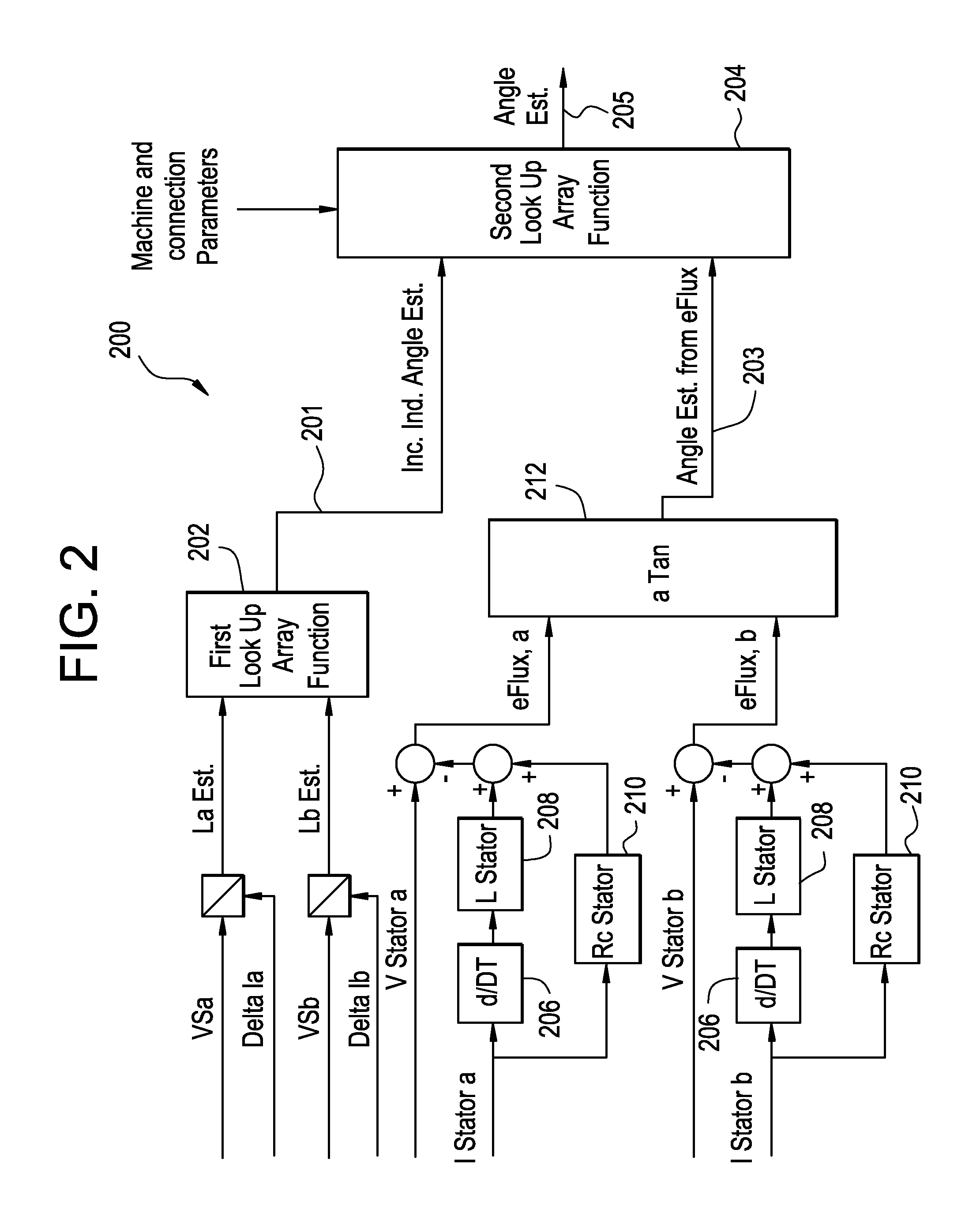
A method for determining rotor position comprising sending a signal to a stator, receiving a first signal indicative of a first estimated stator inductance, and receiving a second signal indicative of a second estimated stator inductance. The method further includes, calculating a first rotor position angle using a function including the first estimated stator inductance and the second estimated stator inductance.

Description

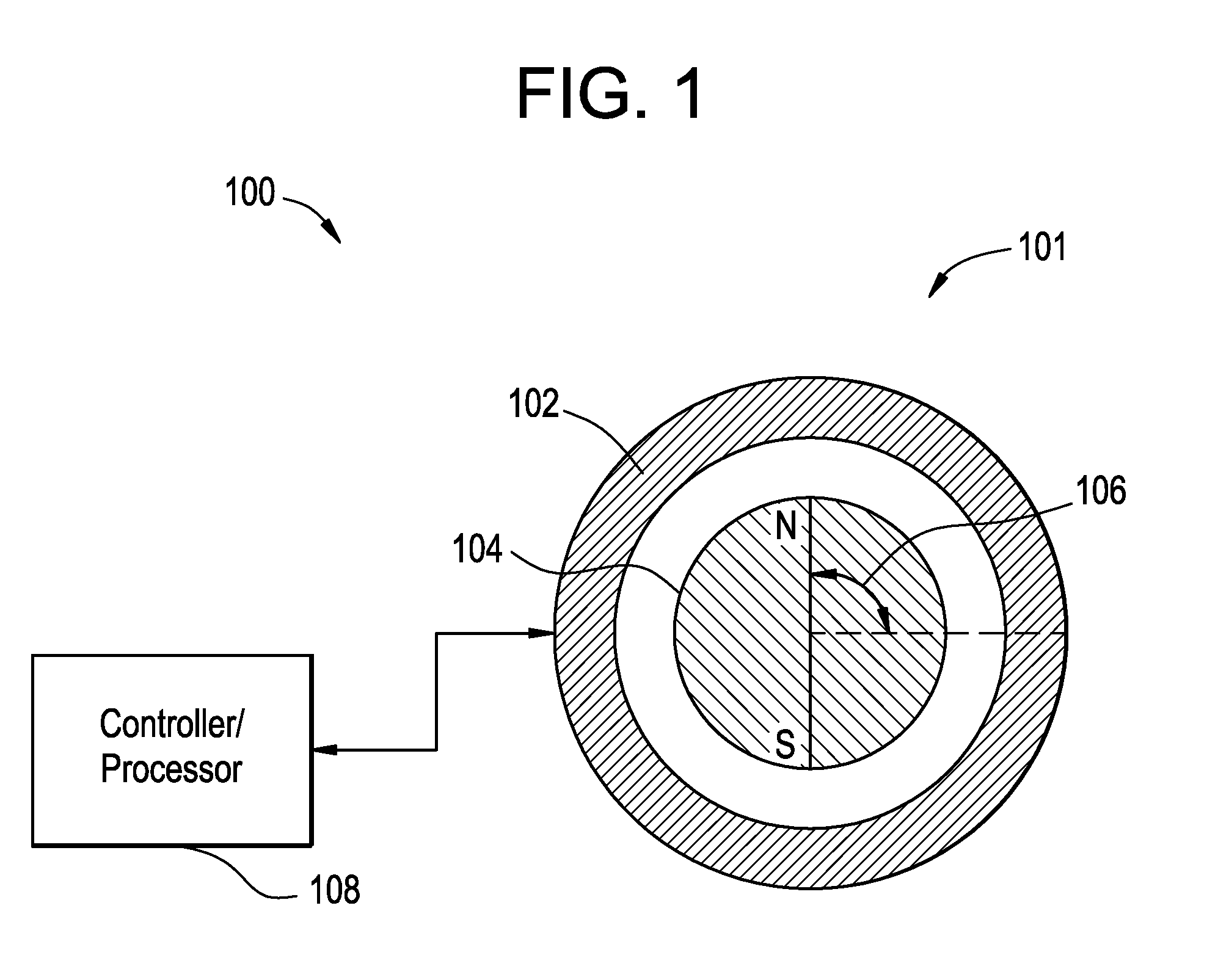
BACKGROUND OF THE INVENTION[0001]The subject invention relates to determining the position of a rotor in a machine such as a motor or a generator. More particularly, the subject invention relates to determining the position of a rotor by identifying an axis of magnetization.[0002]Identifying the axis of magnetization of a machine allows the control of a power flow in the machine. Machines that use rotors with permanent magnets often use sensors to identify the axis of magnetization. Sensors increase the complexity of a system, and may be undesirable. Combining Terminal voltage and line current into an estimation of machine EFLUX allows for the identification of the axis of magnetization. The determination of machine EFLUX to identify the axis of magnetization is effective while the machine is operating at high speeds because the machine has a readily measurable EFLUX, however as the Machine terminal voltage decreases with the decrease in speed of the machine, the effectiveness of th...

Claims


Application Information

Patent Timeline
Patent Type & Authority Applications(United States)
IPC IPC(8): H02P6/18
CPCH02P6/185G01D5/2006
Inventor RITTER, ALLEN MICHAELDATTA, RAJIBGARCES, LUIS J.HUANG, XIANGHUI
Owner GENERAL ELECTRIC CO
Learn More