
Method and system for Quality of Service (QoS) monitoring for wireless devices

a wireless device and quality of service technology, applied in the field of quality of service (qos) monitoring of packetbased wireless data transmission, can solve the problems of reducing communication efficiency, increasing cost and complexity for mobile network operators and companies, and not designed for rich multimedia wireless data services in 1g and 2g wireless systems

Inactive Publication Date: 2010-01-28
ROOT WIRELESS
View PDF5 Cites 81 Cited by
  • Summary
  • Abstract
  • Description
  • Claims
  • Application Information

AI Technical Summary

Benefits of technology

"The present invention provides a method for monitoring the quality of service in a wireless network that includes a wireless device and a fixed transceiver. This is done by processing quality of service data and wirelessly providing it to the fixed transceiver. The invention also includes a wireless device that includes a transceiver, a processor, and a messaging device for providing processed data to the wireless network. The technical effect of this invention is to enable improved quality of service monitoring in wireless networks."

Problems solved by technology

However, the 1G and 2G wireless systems are not designed to handle rich multimedia wireless data services in an “always-on” packet-based wireless environment, which mobile users are demanding.
Unfortunately, both 2.5G and 3G technologies are proving to have several problems with respect to managing their QoS levels.
Therefore, what is needed is a method and system to monitor QoS in networks including mobile devices without reducing communication efficiency and increasing cost and complexity for mobile network operators and companies.

Method used


Image

  • Method and system for Quality of Service (QoS) monitoring for wireless devices
  • Method and system for Quality of Service (QoS) monitoring for wireless devices
  • Method and system for Quality of Service (QoS) monitoring for wireless devices

Examples


Embodiment Construction

[0034]In the following description, numerous specific details are set forth to provide a more thorough understanding of the present invention. However, it will be apparent to one of skill in the art that the present invention may be practiced without one or more of these specific details. In other instances, well-known features have not been described in order to avoid obscuring the present invention.

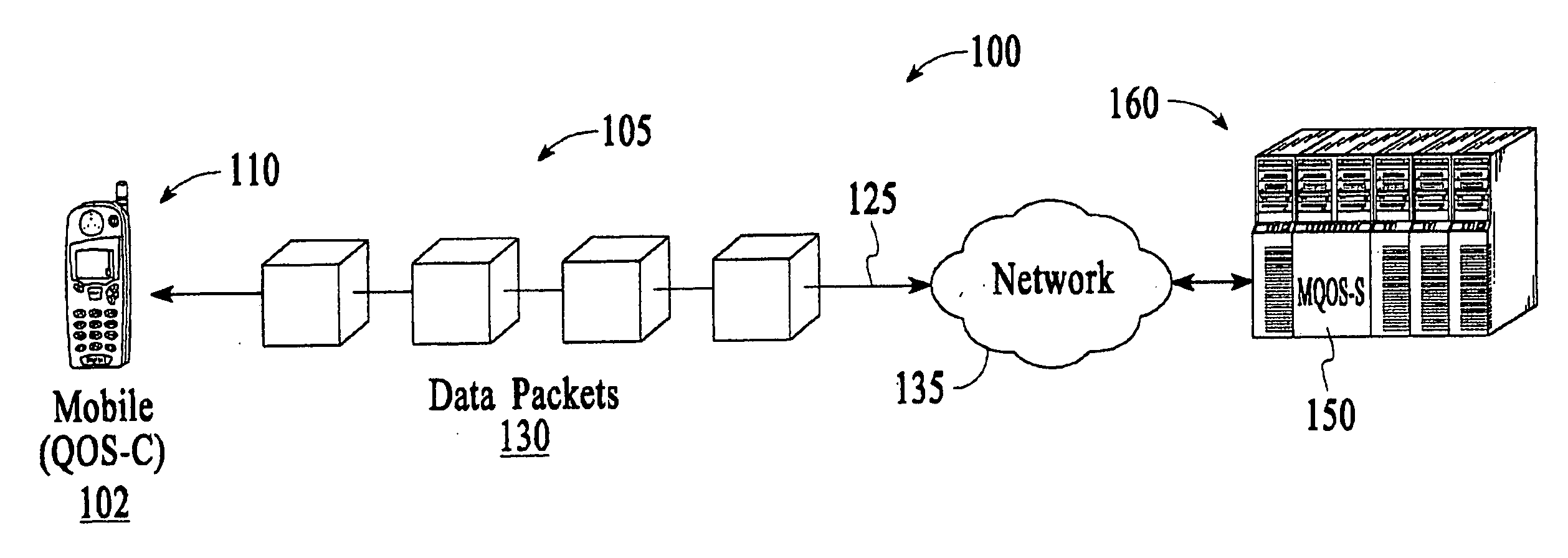
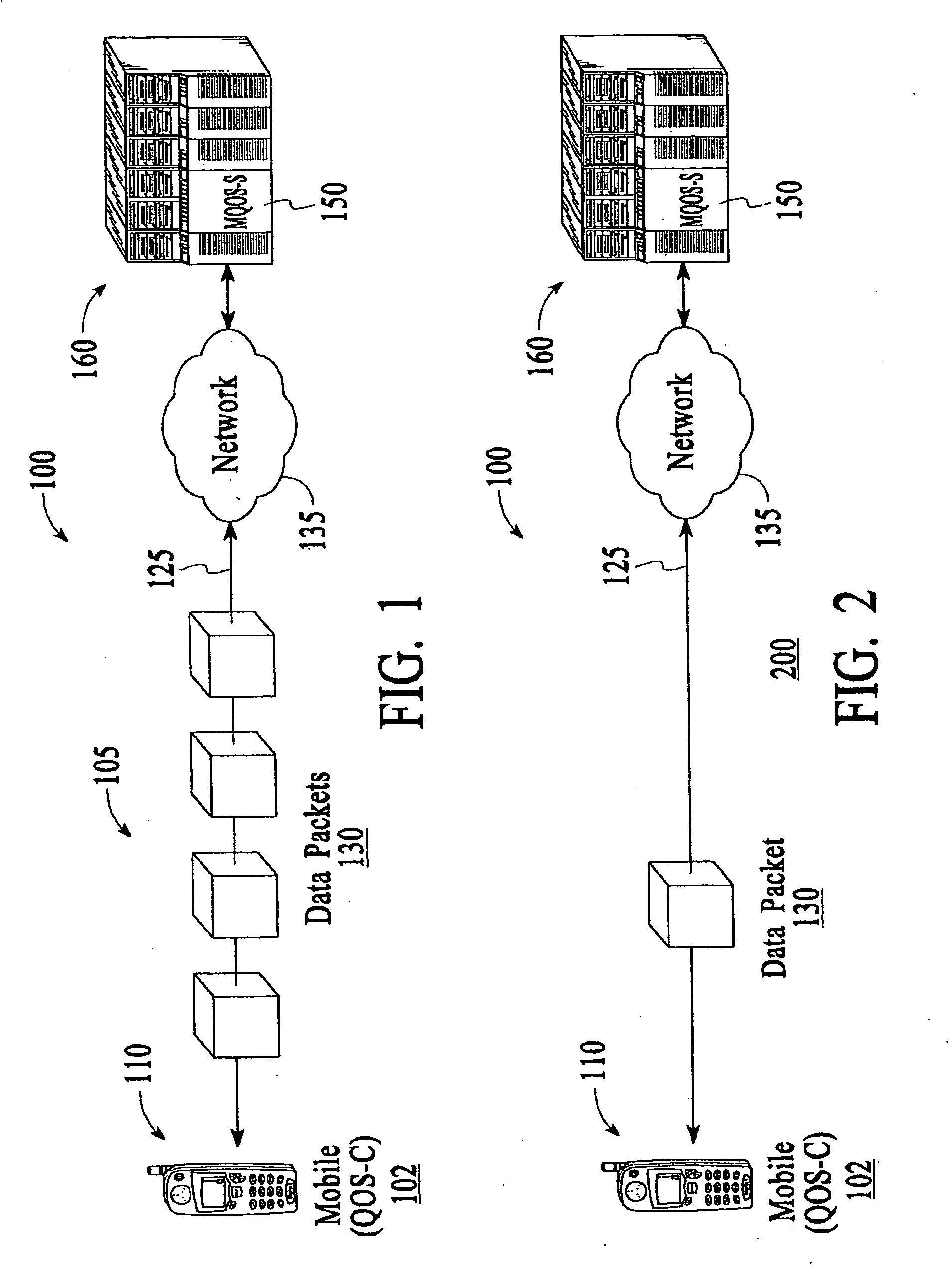
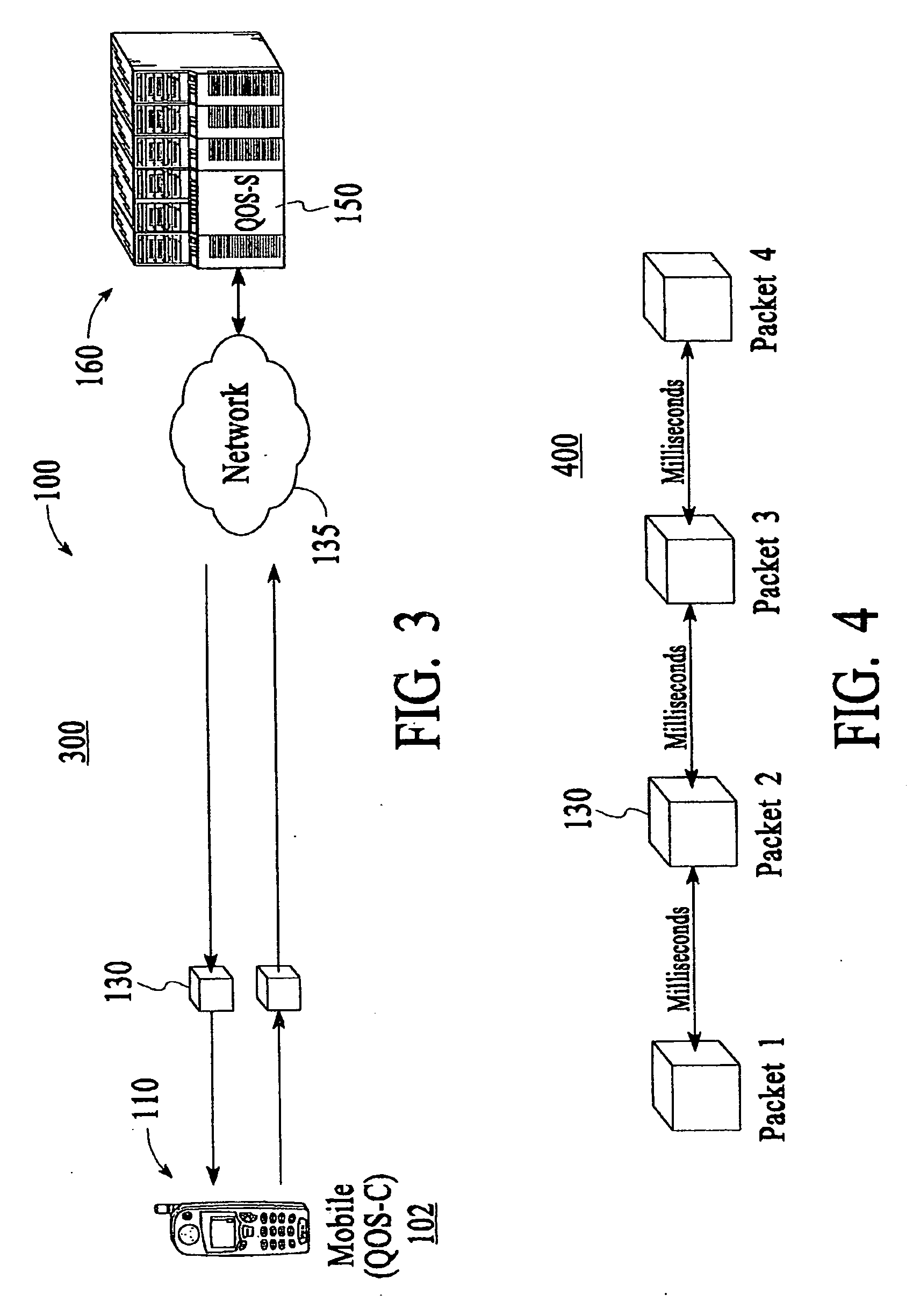
[0035]Generally, the present invention is a Quality of Service (QoS) system that is particularly well suited for the needs of packet-based wireless network environments such as 2.5G, 3G, and the like. The present invention is described in terms of a packet-based network environment described with specification and standards such as 3GPP, however other standards are contemplated. Monitoring mobile QoS (MQoS) on a subscriber-specific basis within mobile devices may be referred to herein as Quality of Experience (QoE), a term developed by the inventors as an aspect of the present invention...


PUM


Abstract

Method and apparatus to monitor MQoS of wireless mobile devices is described. In one embodiment, the present invention provides a method to monitor the health of 3G mobile devices and provide a status check of such health to network technicians, supervisors, and management. In one aspect, mobile devices on the network perform measurement of MQoS factors that are reported to a quality of service backend. The MQoS data is combined to show current and historical network status. In another aspect, alarms may be set to notify specific managers when manager programmable conditions occur, such as low system performance, or specific error conditions occur. Reports may be generated summarizing and illustrating performance in tabular and graphical form. Parameters used for testing and monitoring mobile devices may be input to specific mobile devices or groups of mobile devices in a system. In one aspect, customer care or call centers may be enabled to request specific tests from specific mobile devices and utilize the overall network status to diagnose and / or resolve customer issues.

Description

CROSS-REFERENCE TO RELATED APPLICATIONS[0001]This is a Divisional Application of U.S. patent application Ser. No. 10 / 393,600 of the same title, issuing as U.S. Pat. No. 7,596,373 on Sep. 29, 2009. The present invention is also based on U.S. Provision Patent Application Ser. No. 60 / 366,787, filed Mar. 21, 2002, entitled “Method and System for Quality of Service (QoS) Monitoring for 3G Handset Devices,” filed in the name of Christopher M. McGregor, et al. The priority of this provisional application is hereby claimed and it is hereby incorporated herein by reference thereto.BACKGROUND OF THE INVENTION[0002]1. Field of the Invention[0003]Embodiments of the present invention generally relate to Quality of Service (QoS) monitoring of packet-based wireless data transmissions. More specifically, the present invention relates to QoS of wireless mobile devices.[0004]2. Description of the Related Art[0005]Generally, a communication system includes a transmitter and receiver that transmit and ...

Claims


Application Information

Patent Timeline
Patent Type & Authority Applications(United States)
IPC IPC(8): H04L12/26H04B17/00H04W24/00
CPCH04B17/309H04B17/23H04W24/00H04W24/08H04M3/2227H04M7/0084H04M2207/185H04B17/24
Inventor MCGREGOR, CHRISTOPHER M.MCGREGOR, GREGORY M.
Owner ROOT WIRELESS
Learn More