Thin film wound dressing

a wound dressing and thin film technology, applied in the field of wound dressings, can solve problems such as present difficulties in the application of wound dressings to wound sites

Active Publication Date: 2010-01-21
SMITH & NEPHEW INC
View PDF37 Cites 25 Cited by
  • Summary
  • Abstract
  • Description
  • Claims
  • Application Information

AI Technical Summary

Problems solved by technology

The flexibility of a thin film dressing may, however, present difficulties in the application of the dressing to a wound site.

Method used


Image

  • Thin film wound dressing
  • Thin film wound dressing
  • Thin film wound dressing

Examples


Embodiment Construction

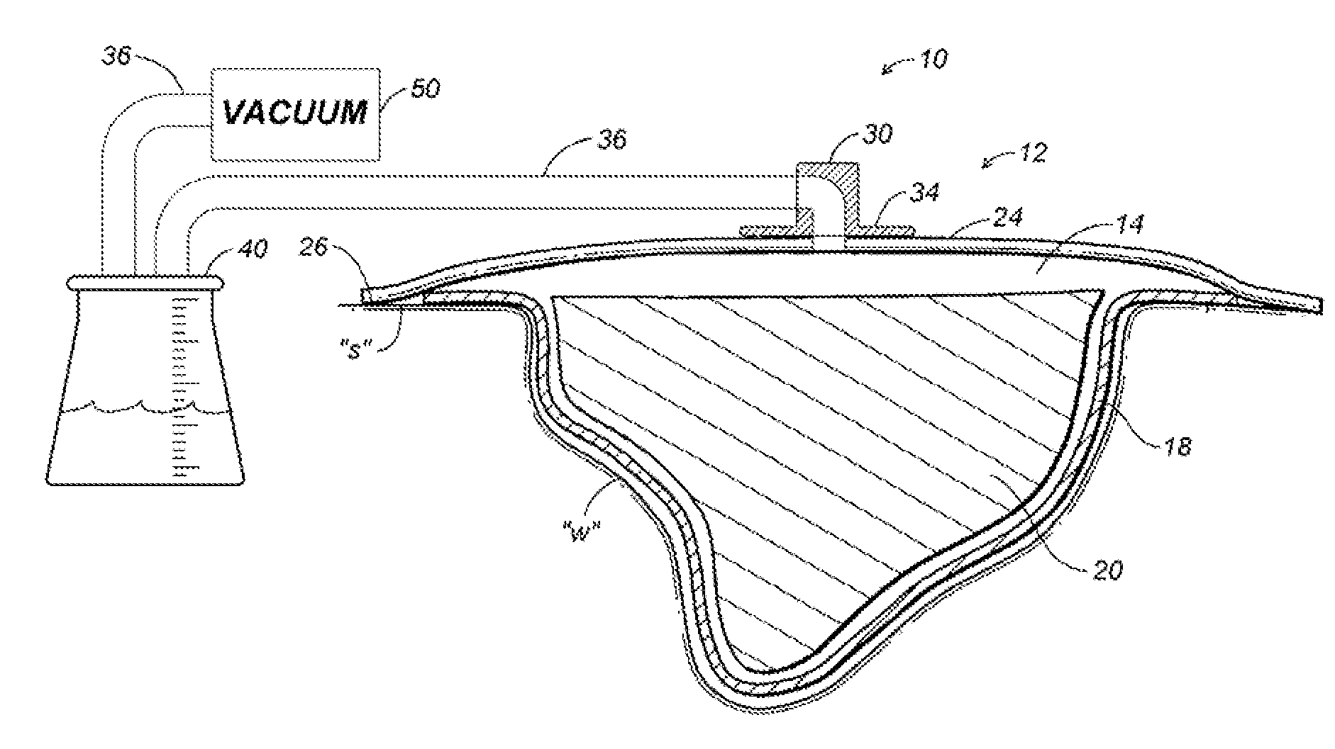
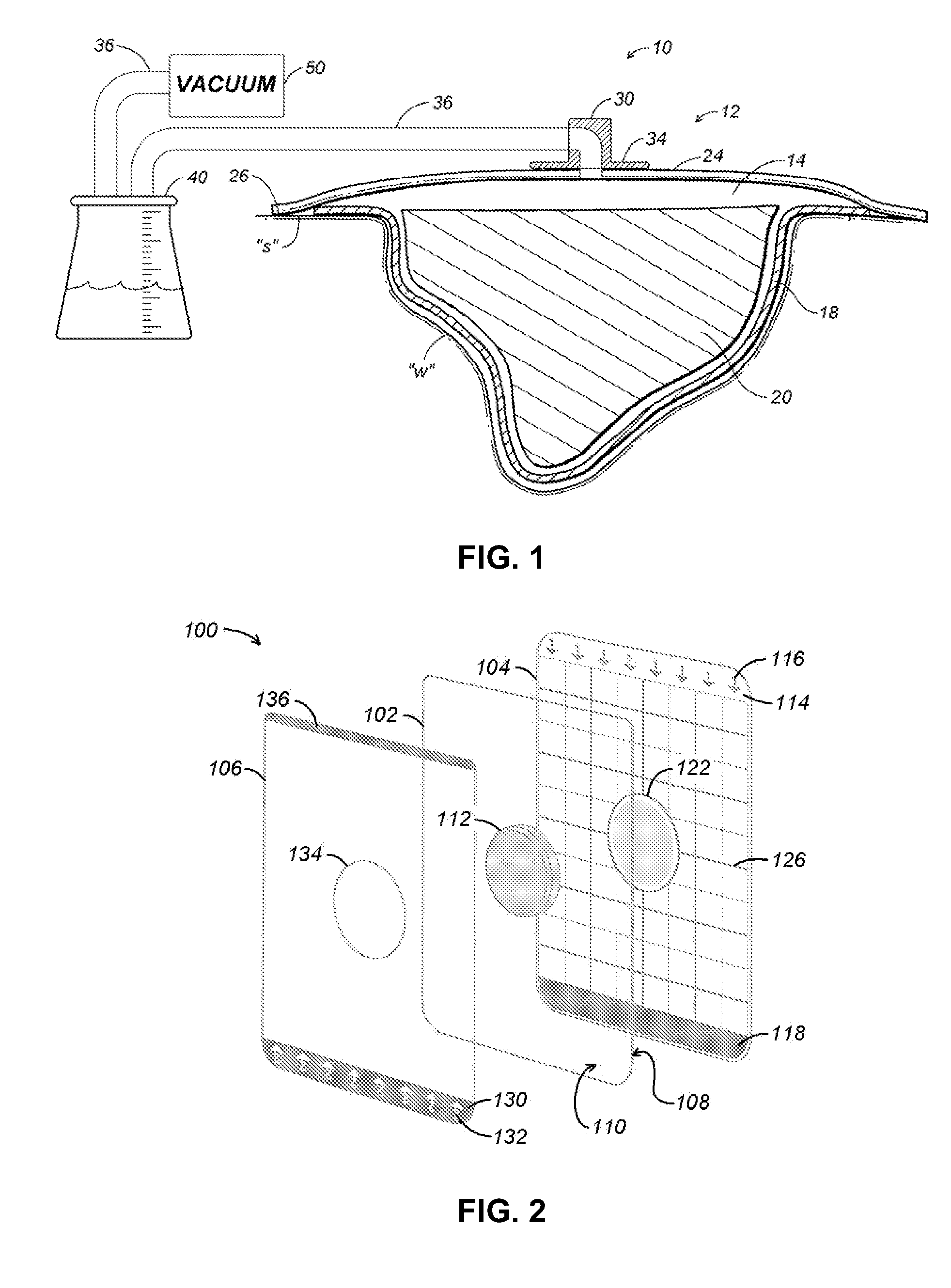
[0027]Referring initially to FIG. 1, a conventional NWPT apparatus is depicted generally as 10 for use on a wound “w” surrounded by healthy skin “s.” The NWPT apparatus 10 includes a wound dressing 12 positioned relative to the wound “w” to define a reservoir 14 in which a negative pressure appropriate to stimulate healing may be maintained.

[0028]Wound dressing 12 includes a contact layer 18 positioned in direct contact with the bed of wound “w” and may be formed from perforated film material. An appropriate perforated material permits the negative pressure applied to the reservoir to penetrate into the wound “w,” and also permits exudates to be drawn through the contact layer 18. Passage of wound fluid through the contact layer 18 is preferably unidirectional such that exudates do not flow back into the wound bed. Unidirectional flow may be encouraged by conical or directional apertures formed in the contact layer 18, or a lamination of materials having absorption properties differ...


PUM


Abstract

A composite wound dressing and delivery apparatus includes a substantially transparent dressing layer having a lower surface that is coated with a pressure sensitive for applying the dressing layer over a wound to define a reservoir in which a negative pressure may be maintained. A substantially transparent backing layer adhered to the lower surface of the dressing layer in a releasable manner, and a vacuum port is centrally located on the dressing layer. The vacuum port is adapted to provide fluid communication between a vacuum source and the reservoir through the dressing layer. A targeting grid associated with either the dressing layer or the backing layer includes regularly spaced reference marks along at least two axes extending from the vacuum port.

Description

BACKGROUND[0001]1. Technical Field[0002]The present disclosure relates generally wound dressings, and in particular to a delivery apparatus for the application of thin film dressings over a wound for use in a treatment such as negative wound pressure therapy.[0003]2. Background of Related Art[0004]Wound dressings are generally placed over a wound to protect and promote healing of the wound. One type of wound dressing consists essentially of a thin membrane of a polymer or similar material, coated on an underside with a pressure-sensitive adhesive. The adhesive may adhere the dressing to healthy skin surrounding the wound such that the dressing provides an effective bacterial barrier to protect the wound from contamination. Because of their extremely elastic nature, thin polymeric film dressings may readily conform to irregular contours of a patient's skin while promoting patient movement and comfort. This type of dressing may also be sufficiently transparent to permit visual inspect...

Claims


Application Information

Patent Timeline
Patent Type & Authority Applications(United States)
IPC IPC(8): A61F13/00A61M1/00A61M27/00
CPCA61F13/00068A61F13/00085A61F13/0226A61F2013/00174A61M27/00A61F2013/00536A61F2013/0054A61F2013/00851A61M1/0088A61F2013/00182A61M2210/086A61M1/982A61M1/915A61M1/916A61F13/0216
Inventor VITARIS, RONALD F.ANDERSON, ROSEMCKEOWN, DEIRDRERUGGLES, ADAM M.
Owner SMITH & NEPHEW INC
Why Eureka
Try Eureka